All airspace active multi beam spherical phased array antenna direction diagram measurement system

A phased array antenna and measurement system technology, which is applied in the antenna radiation pattern and other directions, can solve the problems of difficult to realize external size antenna, high cost, and high requirements for rotation, and achieve low environmental dependence, fast scanning speed, and easy construction. easy effect

Active Publication Date: 2014-10-15
10TH RES INST OF CETC
View PDF4 Cites 61 Cited by
  • Summary
  • Abstract
  • Description
  • Claims
  • Application Information

AI Technical Summary

Problems solved by technology

[0005] 1. The cost of building a test environment for near-field measurement in a microwave anechoic chamber environment is high, and it is even difficult to realize the antenna with a large external size;
[0006] 2. The far-field measurement method of the conventional free-space test environment i

Method used


Image

  • All airspace active multi beam spherical phased array antenna direction diagram measurement system
  • All airspace active multi beam spherical phased array antenna direction diagram measurement system

Examples


Embodiment Construction

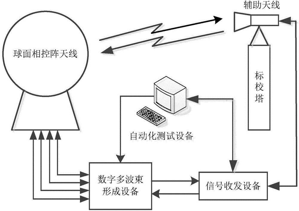
[0020] refer to Figure 1 ~ Figure 2 . figure 1 The structure of the full-airspace active multi-beam spherical phased array antenna pattern measurement system shown is mainly composed of spherical phased array antenna, calibration tower, auxiliary antenna, active digital multi-beam forming equipment, signal transceiver equipment, and automated testing equipment . Among them, the rear end of the spherical phased array antenna is connected to the active digital multi-beam forming equipment, the calibration tower is built according to the position of the antenna, the auxiliary antenna for sending and receiving test signals is placed on the calibration tower, and the auxiliary antenna on the calibration tower The distance between the antenna and the spherical phased array antenna to be tested satisfies the minimum far-field distance condition.

[0021] The implementation steps of testing the receiving pattern are as follows:

[0022] 1. Build a receiving test link: the signal t...


PUM


Abstract

The invention provides an all airspace active multi beam spherical phased array antenna direction diagram measurement system. The provided measurement system has the advantages of flexible control, high directional accuracy and low cost, and uses electric scanning to replace mechanical scanning. According to the technical scheme provided by the invention, when a direction diagram test link is received, a signal transmitting and receiving device transmits a test frequency point signal to an auxiliary antenna of a calibration tower; a spherical phased array antenna receives a signal transmitted by the auxiliary antenna; a receiving beam is formed through an active digital multi-beam forming device; the signal transmitting and receiving device receives and records the signal level, and reports the signal level to automation test software of an automation test device; the automation test software of the automation test device controls the active digital multi-beam forming device to form a transmitting and receiving beam in a certain direction and acquire the signal level of the transmitting and receiving beam; two-dimensional electric scanning is carried out on the whole airspace; and three-dimensional images are respectively drawn for the directional azimuth and the elevation angle of the transmitting and receiving beam, and the signal level corresponding to the direction, so as to acquire a transmitting and receiving three-dimensional direction diagram of the antenna.

Description

technical field [0001] The invention relates to a system structure for measuring the pattern of an all-space active multi-beam spherical phased array antenna. Background technique [0002] In recent years, as an important development direction of civil and military antenna technology, phased array antenna has attracted much attention. In the phased array antenna, the active multi-beam antenna signal transceiver system refers to the ability to generate two or more independently controllable beams, and each beam can be aimed at the target, and the signal transmission to each target can be completed independently. or receive. The beam of the phased array antenna is controlled by a computer, and it scans almost without inertia in space. It has great flexibility. The maximum radiation direction of the antenna changes with the flexible beam scanning; in addition, the arrangement of the antenna elements Factors such as element spacing and weighting function all have a great influ...

Claims


Application Information

Patent Timeline
IPC IPC(8): G01R29/10
Inventor 冯林高俄广西赵卫东王文政李兆虎刘云阁
Owner 10TH RES INST OF CETC
Why Eureka
Try Eureka