
PWM signal power-up and power-down protection circuit

A PWM signal, power-down protection technology, applied in electrical components, electronic switches, pulse technology, etc., can solve problems such as inability to work, end-of-life loss of enterprises, damage to semiconductor switching devices, etc., to prolong the service life and save costs.

Active Publication Date: 2014-10-15
NANJING APAITEK TECH
View PDF3 Cites 2 Cited by
  • Summary
  • Abstract
  • Description
  • Claims
  • Application Information

AI Technical Summary

Problems solved by technology

[0007] In the existing application circuit, the circuit will cause certain damage to the semiconductor switching device when the circuit is initially powered on or powered off at a certain level. The degree of this damage will determine the service life of the semiconductor. The semiconductor device may If there is a problem of not being able to work at the beginning, it may also stop working during normal work in the future. This unpreventable life stop will bring certain losses to the enterprise. When a key semiconductor device is damaged, it will often Cause irreparable huge losses, so it is necessary to develop a PWM signal power-on and power-down protection circuit to solve the problems and deficiencies in the existing technology

Method used


Image

  • PWM signal power-up and power-down protection circuit
  • PWM signal power-up and power-down protection circuit

Examples


Embodiment Construction

[0052] Embodiments of the present invention are described in detail below, examples of which are shown in the drawings, wherein the same or similar reference numerals denote the same or similar elements or elements having the same or similar functions throughout. The embodiments described below by referring to the figures are exemplary only for explaining the present invention and should not be construed as limiting the present invention.

[0053] Those skilled in the art will understand that unless otherwise stated, the singular forms "a", "an", "said" and "the" used herein may also include plural forms. It should be further understood that the word "comprising" used in the description of the present invention refers to the presence of said features, integers, steps, operations, elements and / or components, but does not exclude the presence or addition of one or more other features, Integers, steps, operations, elements, components, and / or groups thereof. It will be understoo...


PUM


Abstract

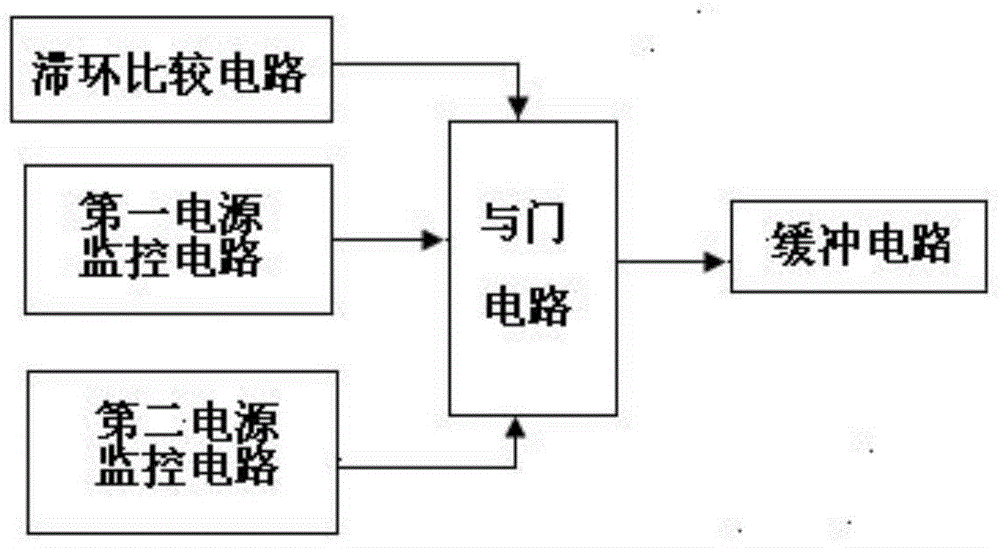
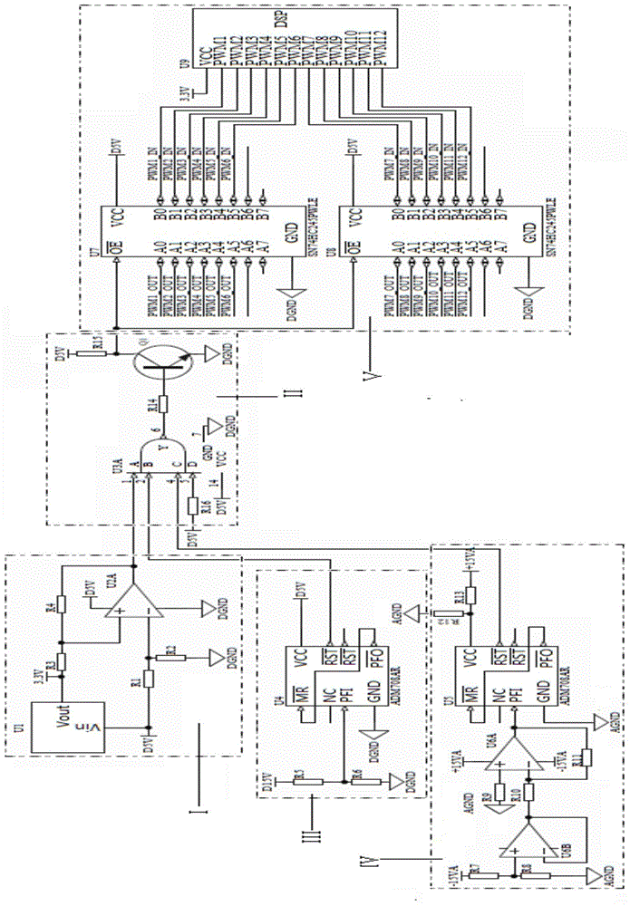
The invention discloses a PWM signal power-up and power-down protection circuit comprising a hysteresis comparison circuit, an AND gate circuit, a first power supply monitoring circuit, a second power supply monitoring circuit and a buffer circuit. The AND gate circuit is respectively connected with the hysteresis comparison circuit, the first power supply monitoring circuit, the second power supply monitoring circuit and the buffer circuit. The power supply monitoring and comparison circuits are arranged so that the situation of circuit power supply can be monitored at any time. When the circuit is in the power-up state and voltage is lower than the preset threshold value, output of a PWM signal is limited. When the circuit is in the power-off state, the arranged triode is not conducted, output of the PWM signal from the buffer module is prohibited and thus the PWM signal is locked and a semiconductor device is protected. When the circuit is in the power-up state, the PWM signal is unlocked when all stages of level reaches a certain limit so that damage to the semiconductor switch device caused by initial power-up or power-down of certain stage of level is avoided, the service life of the semiconductor switch device is prolonged and product cost is saved.

Description

technical field [0001] The invention discloses a PWM signal power-up and power-down protection circuit, which belongs to the technical field of circuit design. Background technique [0002] With the rapid development and maturity of power electronics technology, the application of active filter products in power systems is increasing. The PWM signal controls the on and off of the semiconductor switching device, so that the output terminal obtains a series of pulses with equal amplitude and unequal width, and these pulses are used to replace sine waves or other required waveforms. The width of each pulse is modulated according to certain rules, which can not only change the output voltage of the inverter circuit, but also change the output frequency. [0003] PWM is a method of digitally encoding the level of an analog signal. Through the use of high-resolution counters, the duty cycle of the square wave is modulated to encode the level of a specific analog signal. The PWM...

Claims


Application Information

Patent Timeline
IPC IPC(8): H03K17/08
Inventor 郑静花跃学仇志凌张东芮国强温小林张明李刚
Owner NANJING APAITEK TECH
Learn More