Pneumatic device for measuring internal diameter and external diameter of thin-wall bearing ring

A thin-walled bearing and pneumatic measurement technology, which is applied in the field of testing, can solve problems that affect the surface quality of the tested part, easily produce marks on the tested surface, and cannot be effectively measured, so as to achieve small error, small measurement force and long service life Effect

Inactive Publication Date: 2014-10-22
HANGZHOU DIANZI UNIV
View PDF7 Cites 15 Cited by
  • Summary
  • Abstract
  • Description
  • Claims
  • Application Information

AI Technical Summary

Problems solved by technology

[0002] At present, the thinnest wall thickness of small and medium-sized bearing rings is only 0.275mm. The size and shape and position tolerances of thin-walled bearing rings are easily deformed by traditional mechanical measuring instruments and cannot be effectively measured; and due to the influence of measuring force, they are It is easy to produce marks on the measured surface, which affects the surface quality of the tested part
This problem is a big problem in bearing processing and even in the machinery industry, especially in the production process of military bearing rings. It has special requirements for flexible bearing rings: for controlling the average value of the inner diameter and outer diameter of finished parts, There is currently no effective method of measuring

Method used


Image

  • Pneumatic device for measuring internal diameter and external diameter of thin-wall bearing ring
  • Pneumatic device for measuring internal diameter and external diameter of thin-wall bearing ring
  • Pneumatic device for measuring internal diameter and external diameter of thin-wall bearing ring

Examples


Embodiment Construction

[0024] The present invention will be further described below in conjunction with the accompanying drawings and embodiments.

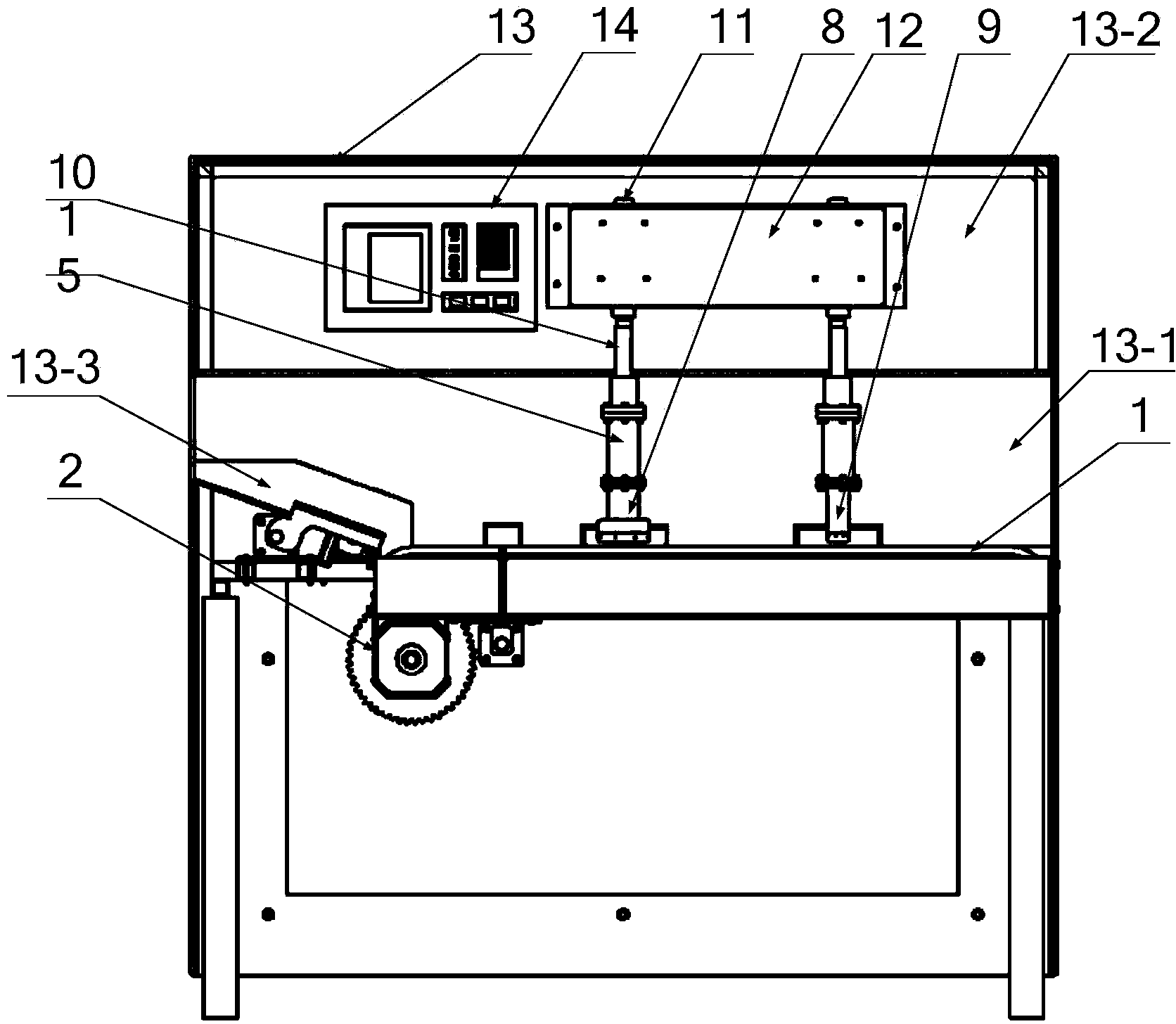
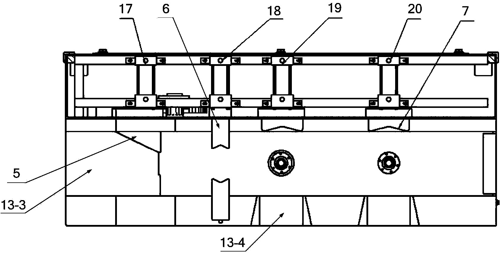
[0025] Such as figure 1 and 2 As shown, a pneumatic measuring device for inner and outer diameters of thin-walled bearing rings includes a conveyor belt 1, a stepping motor 2, a baffle plate 5, a centering fixture 6, a screening push plate 7, an outer diameter measuring head 8, an inner diameter measuring head 9, Control panel 14 , measuring drive, valve cylinder 17 , centering cylinder 18 , first screening cylinder 19 and second screening cylinder 20 .

[0026] A detection chamber 13-1 is provided in the middle of the detection box 13, and a motor installation chamber 13-2 is provided on the top; a slant plate 13-3 is fixed at one end of the detection chamber 13-1, and two collection slots 13-4 are provided on one side ; Two valve cylinders 17 are respectively arranged on both sides of the detection chamber 13-1, and the piston rod of each valve cyli...


PUM


Abstract

The invention discloses a pneumatic device for measuring internal diameter and external diameter of a thin-wall bearing ring. A thin-wall bearing ring easily deforms and generates test marks on the surface due to measurement by a traditional mechanical measurement instrument. The device provided by the invention comprises a conveying belt, a stepper motor, a central fixture, an external diameter measuring head, an internal diameter measuring head, a measuring driving device and a central cylinder. The stepping motor drives the conveying belt; the external diameter measuring head and the internal diameter measuring head both include an upper measuring head and a lower measuring head; an upper airway of the upper measuring head is communicated with plurality of lower airways of the lower measuring head; a side wall of each back pressure sensor connection hole is connected with the is communicated with one lower airway; each back pressure sensor connection hole is provided with the hole a pressure sensor; each back pressure sensor connection hole of the external diameter measuring head is provided with a measuring nozzle; and the outer end of each back pressure sensor connection hole of the internal diameter measuring head is provided with a measuring nozzle. The invention adopts pneumatic measurement mode for measuring the internal diameter and external diameter of thin-wall bearing ring, and the surface of the measured part will not be scratched and can keep the geometrical shape.

Description

technical field [0001] The invention belongs to the technical field of testing, and relates to a bearing testing device, in particular to a pneumatic measuring device for inner and outer diameters of thin-walled bearing rings. Background technique [0002] At present, the thinnest wall thickness of small and medium-sized bearing rings is only 0.275mm. The size and shape and position tolerances of thin-walled bearing rings are easily deformed by traditional mechanical measuring instruments and cannot be effectively measured; and due to the influence of measuring force, they are It is easy to produce marks on the measured surface, which affects the surface quality of the tested part. This problem is a big problem in bearing processing and even in the machinery industry, especially in the production process of military bearing rings. It has special requirements for flexible bearing rings: for controlling the average value of the inner diameter and outer diameter of finished par...

Claims


Application Information

Patent Timeline
IPC IPC(8): B07C5/04B07C5/36G01B13/08G01B13/10
Inventor 吴参沈进文倪敬李兴林
Owner HANGZHOU DIANZI UNIV
Why Eureka
Try Eureka