Sputtering equipment and sputtering method

A sputtering and equipment technology, applied in the field of coating equipment, can solve the problems of large footprint, high cost, complex structure, etc., achieve continuous sputtering, simplify the process, and improve sputtering efficiency

Inactive Publication Date: 2014-10-22
EVERDISPLAY OPTRONICS (SHANGHAI) CO LTD
View PDF4 Cites 4 Cited by
  • Summary
  • Abstract
  • Description
  • Claims
  • Application Information

AI Technical Summary

Problems solved by technology

In order to improve production efficiency, a plurality of ITO sputtering chambers 1' and Ag sputtering chambers 2' are generally arranged on the same equipment, but the above-mentioned multi-chamber equipment has a complex structure, a large footprint, and relatively high cost. high

Method used


Image

  • Sputtering equipment and sputtering method
  • Sputtering equipment and sputtering method
  • Sputtering equipment and sputtering method

Examples


Embodiment Construction

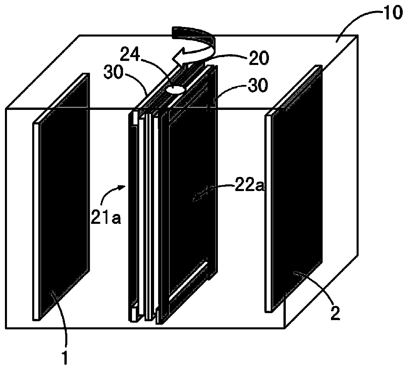
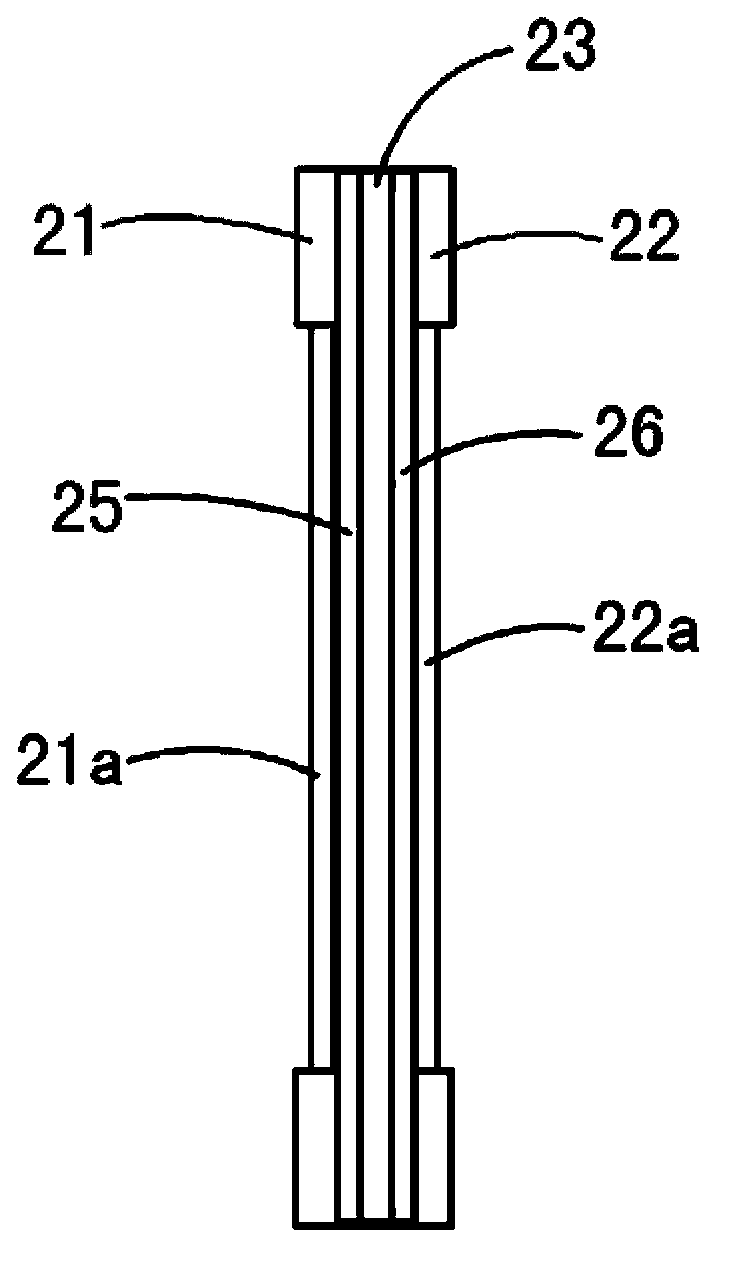
[0021] Figure 2A Shown as a schematic diagram of sputtering equipment in an embodiment of the present invention. Figure 2B shown as Figure 2A A schematic diagram of the rotating target mechanism 20 of the sputtering device.

[0022] Such as Figure 2A As shown, the sputtering equipment in one embodiment of the present invention includes a cavity 10 , a rotating target mechanism 20 and two sets of sealing mechanisms 30 . In operation, the first substrate 1 and the second substrate 2 may be disposed in a sputtering apparatus.

[0023] The cavity 10 is in the shape of a cuboid in this embodiment, and may be in any other shape in other embodiments.

[0024] The rotating target mechanism 20 is arranged in the cavity 10, and as Figure 2B As shown, it includes a first target fixture 21 , a second target fixture 22 , an insulating layer 23 and a rotating shaft 24 between the first target fixture 21 and the second target fixture 22 .

[0025] In this embodiment, the first tar...


PUM


Abstract

The invention discloses sputtering equipment and a sputtering method. The sputtering equipment comprises a cavity; and a rotary target material mechanism, which is arranged in the middle part of the cavity, wherein the two opposite sides of the target material mechanism are respectively provided with a first target material and a second target material. The rotary target material mechanism comprises a rotary shaft, and is capable of rotating around the rotary shaft. The rotary target material mechanism also comprises a sealing mechanism, which is arranged on the two sides of the rotary target material mechanism. The sealing mechanism couples the rotary target material mechanism and the cavity so as to divide the cavity into two enclosed chambers. A first substrate and a second substrate are respectively arranged in the chambers. The rotary target material mechanism comprise a first target material fixing member and a second target material fixing member, which are oppositely arranged and are used to fixed the first target material and the second target material respectively. The sputtering equipment is provided with a rotary target material mechanism, so the equipment can sputter two kinds of coated films in the same cavity at the same time, moreover, continuous sputtering is also achieved, and the sputtering efficiency is improved.

Description

technical field [0001] The invention relates to a coating device, in particular to a sputtering device. Background technique [0002] Sputtering (sputter) is an excellent coating process. It is a DC glow discharge generated by applying high voltage to both ends of the electrode in a vacuum environment, so that the introduced process gas is ionized, and the positive ions bombard the target at a high speed under the action of an electric field, and the escaped Target atoms and molecules are deposited onto the surface of the substrate to be coated. The sputtering process has the advantages of good film quality and fast speed, and is widely used in the thin film field effect transistor (TFT) industry. However, in actual use, sometimes it is necessary to continuously coat two different films, and the materials of these two films will have cross-contamination, so they cannot be operated in the same process chamber. [0003] For example, the ITO / Ag / ITO film structure widely used ...

Claims


Application Information

Patent Timeline
Patent Type & Authority Applications(China)
IPC IPC(8): C23C14/34
Inventor 许民庆储培鸣
Owner EVERDISPLAY OPTRONICS (SHANGHAI) CO LTD
Why Eureka
Try Eureka