

Refrigerant compressor
A refrigerant and compressor technology, applied in additives, mechanical equipment, machines/engines, etc., can solve problems such as refrigerant vaporization
- Summary
- Abstract
- Description
- Claims
- Application Information
AI Technical Summary
Problems solved by technology
Method used
Image

Examples
Embodiment approach 1
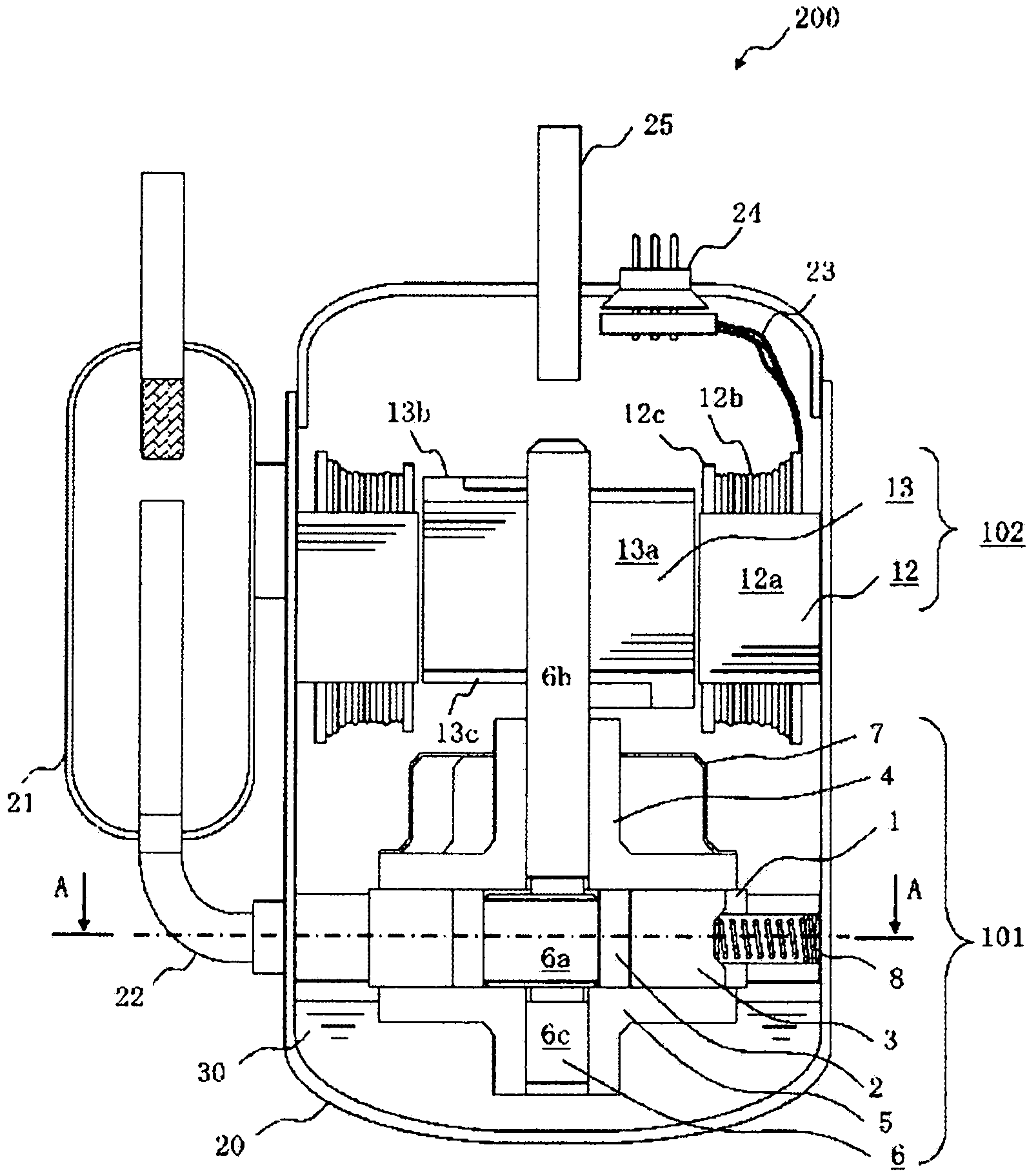
[0022] Hereinafter, an embodiment of the present invention will be described using a rotary compressor as an example of a refrigerant compressor. In addition, although the rotary compressor of one cylinder is demonstrated here, it can implement also in the rotary compressor of several cylinders.
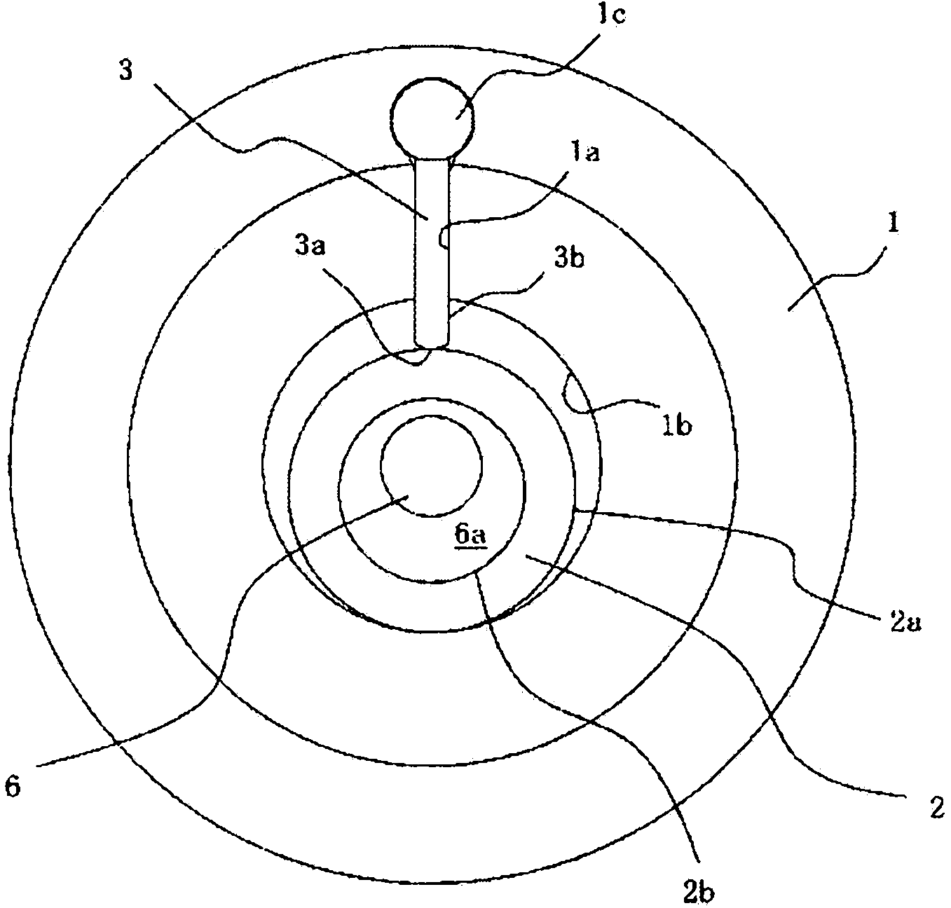
[0023] figure 1 , figure 2 is a diagram showing Embodiment 1, figure 1 is a longitudinal sectional view of the rotary compressor 200, figure 2 is along figure 1 Sectional view of line A-A.
[0024] The overall structure of the rotary compressor 200 will be briefly described.
[0025] figure 1 An example of the rotary compressor 200 shown is a vertical structure in which the inside of the airtight container 20 is high pressure. A compression element 101 is accommodated in a lower portion of the airtight container 20 . An electric element 102 for driving the compression element 101 is accommodated above the compression element 101 in the upper portion of the airtight containe...
Embodiment approach 2
[0079] In Embodiment 1, the method of preventing the polymerization of the refrigerant by sufficient presence of the refrigerator oil containing the polymerization inhibitor in the high-temperature portion was shown, but it is also possible to make the sliding member contain the polymerization inhibitor in advance. This method will be described.
[0080] The cylinder 1 , the main bearing 4 , and the sub-bearing 5 shown in Embodiment 1 can be composed of porous sintered components. After previously impregnating these sintered parts with a polymerization inhibitor or refrigerating machine oil containing a polymerization inhibitor, the compressor is assembled. Thereby, the polymerization inhibitor seeps out from the sintered part in the compressor cylinder and the sliding part, which tend to become high temperature, and has an effect of further enhancing the effect of inhibiting the polymerization of the refrigerant.
[0081] As a result, in a state where the refrigerator oil is...
Embodiment approach 3
[0083] In the winding part of the electric element which tends to become high temperature other than the sliding part, similarly to Embodiment 2, a polymerization inhibitor can be contained in advance. This method will be described.
[0084] In the winding part 12b of the electric element, a gap is generated between the windings in the windings having a circular cross section. The gap between the windings can contain and hold a polymerization inhibitor or refrigerating machine oil containing a polymerization inhibitor similarly to the porosity of the sintered part. For example, the processing oil used in the winding process contains a polymerization inhibitor, or the winding is impregnated with a polymerization inhibitor. Thereby, the polymerization inhibitor in the winding part 12b is fully supplied to the winding part where polymerization occurs, and the effect of suppressing polymerization of a refrigerant|coolant can be heightened.
[0085] As a result, in a state where ...
PUM
| Property | Measurement | Unit |
|---|---|---|
| Plate thickness | aaaaa | aaaaa |
| Dynamic viscosity | aaaaa | aaaaa |
Abstract
Description
Claims
Application Information