

Conformal antenna on holographic artificial impedance surface
An artificial impedance and conformal antenna technology, applied in the field of antennas, can solve problems such as limitations, and achieve the effect of improving antenna performance, low profile, and good sidelobe level
- Summary
- Abstract
- Description
- Claims
- Application Information
AI Technical Summary
Problems solved by technology
Method used
Image


Examples
Embodiment 1
[0034] A holographic artificial impedance surface conformal antenna. The artificial impedance surface structure includes a metal patch, a dielectric layer and a metal layer. The metal layer can be a metal carrier. Metal patches of different sizes correspond to different surface impedances, and the surface impedance distribution is based on holographic The interference pattern distribution of the principle, wherein, the reference wave corresponding to the interference pattern distribution of the holographic principle is a surface wave, and the target wave is a radiation plane wave.
[0035] The back side of the dielectric layer is a metal layer, the front side is uniformly distributed with units of the same size, and metal patches of different sizes are respectively arranged on the units of the same size.
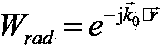
[0036] The target wave is set as a pencil-shaped radiation plane wave, written in the following form: .
[0037] When the reference wave is a cylindrical surface wave,...
Embodiment 2
[0046] This embodiment is described by taking a holographic artificial impedance surface antenna conformal to a conical surface as an example with reference to the accompanying drawings.
[0047] The holographic artificial impedance surface conformal antenna is a new type of antenna that conforms the artificial impedance surface based on the holographic principle to the complex carrier surface. The invention designs a novel leaky-wave antenna by utilizing the holographic principle and impedance modulation theory, and further performs conformal processing on the holographic artificial impedance surface so that it can conform to complex objects. The invention proposes a new reference scheme for the antenna conformal technology, and greatly improves the performance of the antenna.
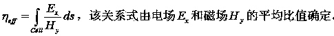
[0048] Take the conical conformal holographic artificial impedance surface antenna as an example. The antenna uses a monopole antenna to feed power on the conical surface, and the surface impedance d...
PUM
 Abstract
Description
Claims
Application Information