Modulator, demodulator, modulation method and demodulation method for low-frequency magnetic induction communication

A magnetic induction and modulator technology, applied in the field of communication, can solve the problems of software demodulation method, such as large amount of calculation, low flexibility, low low frequency communication rate, etc.

Active Publication Date: 2014-10-22
UNIV OF SCI & TECH BEIJING
View PDF5 Cites 19 Cited by
  • Summary
  • Abstract
  • Description
  • Claims
  • Application Information

AI Technical Summary

Problems solved by technology

[0005] The present invention provides a modulator, a demodulator, a modulation method and a demodulation method for low-frequency magnetic induction communication, which are used to solve the problem of low frequency communication rate due to the mutual limitation of the bandwidth and Q value of the transmitting end of the existing low-frequency magnetic induction communication. The hardware demodulation method at the receiving end has low integration and flexibility, and the software demodulation method has the problem of large amount of calculation

Method used


Image

  • Modulator, demodulator, modulation method and demodulation method for low-frequency magnetic induction communication
  • Modulator, demodulator, modulation method and demodulation method for low-frequency magnetic induction communication
  • Modulator, demodulator, modulation method and demodulation method for low-frequency magnetic induction communication

Examples


Embodiment Construction

[0080] In order to make the technical problems, technical solutions and advantages to be solved by the present invention clearer, the following will describe in detail with reference to the drawings and specific embodiments.

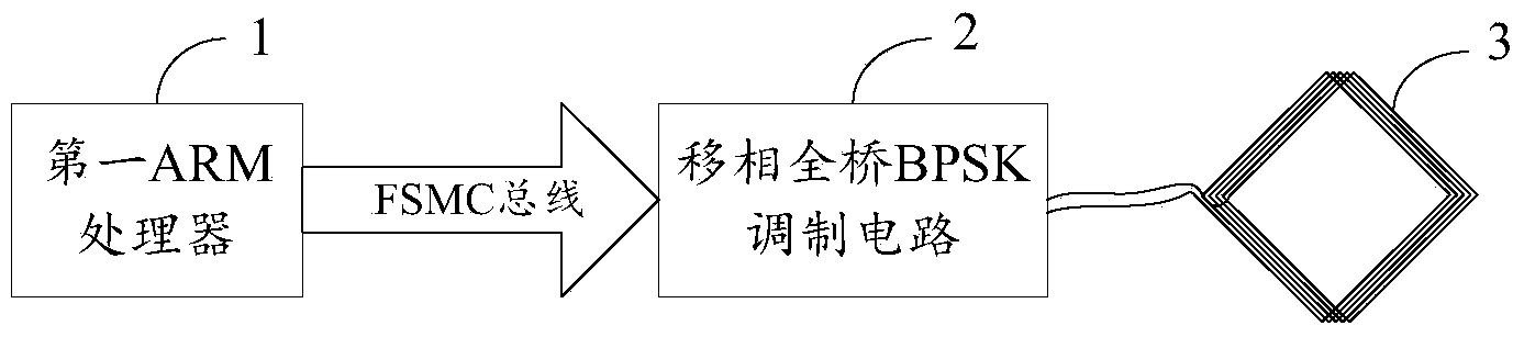
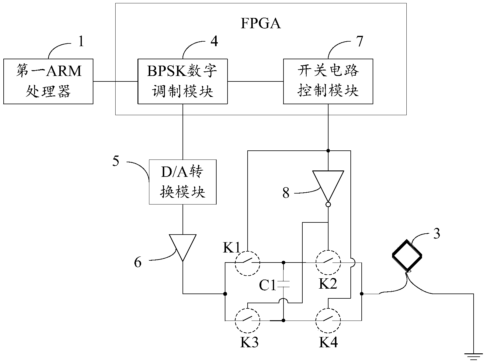
[0081] figure 1 Shown is a schematic structural diagram of a modulator for low-frequency magnetic induction communication provided by an embodiment of the present invention, as shown in figure 1As shown in , the modulator includes: a first ARM processor 1 , a phase-shifted full-bridge BPSK modulation circuit 2 and a low-frequency magnetic induction transmitting antenna 3 . Wherein, the input end of the phase-shifted full-bridge BPSK modulation circuit 2 is connected to the first ARM processor 1 through the FSMC bus, and the output end is connected to the low-frequency magnetic induction transmitting antenna 3 . The first ARM processor 1 performs channel coding on the user data, obtains the symbol sequence to be sent and sends the symbol sequence to the ...


PUM


Abstract

The invention provides a modulator, demodulator, modulation method and demodulation method for low-frequency magnetic induction communication. Therefore, problems of mutual restriction of a bandwidth and a Q value of the existing low-frequency magnetic induction communication transmitting terminal, low low-frequency communication rate, low integration degree and flexibility of the hardwire demodulation mode of the receiving terminal, and large calculation amount of the software demodulation mode in the prior art can be solved. According to the modulator, use data are successively processed by channel coding, BPSK digital modulation, D / A conversion and power amplification and then are inputted into a first series connection resonance loop; voltage physical reversing of the two ends of a first capacitor in the resonance loop is carried out at the time of phase changing of the loop current signal of the first series connection resonance loop, thereby avoiding the loop current signal attenuation. Therefore, the modulation signal bandwidth can be substantially improved on the premise that the Q value is maintained to be high; and the communication rate is improved.

Description

technical field [0001] The invention belongs to the modulation and demodulation technology in the communication field, and in particular relates to a modulator, a demodulator, a modulation method and a demodulation method for low-frequency magnetic induction communication. Background technique [0002] At present, low-frequency magnetic induction communication is widely used in underwater communication and underground communication because of its small antenna size, and it is not affected by multipath effect, propagation delay and fading during propagation. However, the channel under the low-frequency band is a low-rate channel, and how to make the most effective use of the communication channel is a difficult point in the current low-frequency communication technology. [0003] In the prior art, the common low-frequency resonant circuit in the transmitting end of low-frequency magnetic induction communication generally requires a trade-off between the bandwidth and the Q va...

Claims


Application Information

Patent Timeline
Patent Type & Authority Applications(China)
IPC IPC(8): H04L27/20H04L27/22
Inventor 张晓彤黄琪玮马静徐金梧
Owner UNIV OF SCI & TECH BEIJING
Why Eureka
Try Eureka