
Hydraulic feeding and fragmentation mine car of stone sawing machine
A stone sawing machine and hydraulic technology, applied in stone processing tools, stone processing equipment, manufacturing tools, etc., can solve the problems of low production efficiency, complex structure, increased energy consumption, etc., achieve small hydraulic shrinkage, safe and convenient operation , the effect of improving production efficiency
- Summary
- Abstract
- Description
- Claims
- Application Information
AI Technical Summary
Problems solved by technology
Method used
Image

Examples
Embodiment
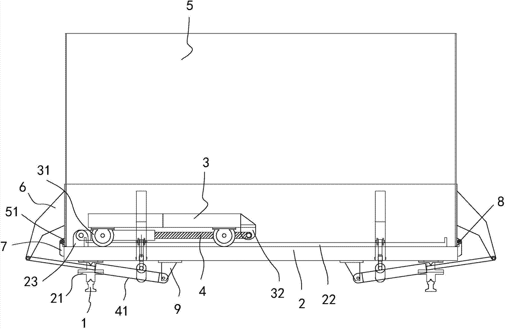
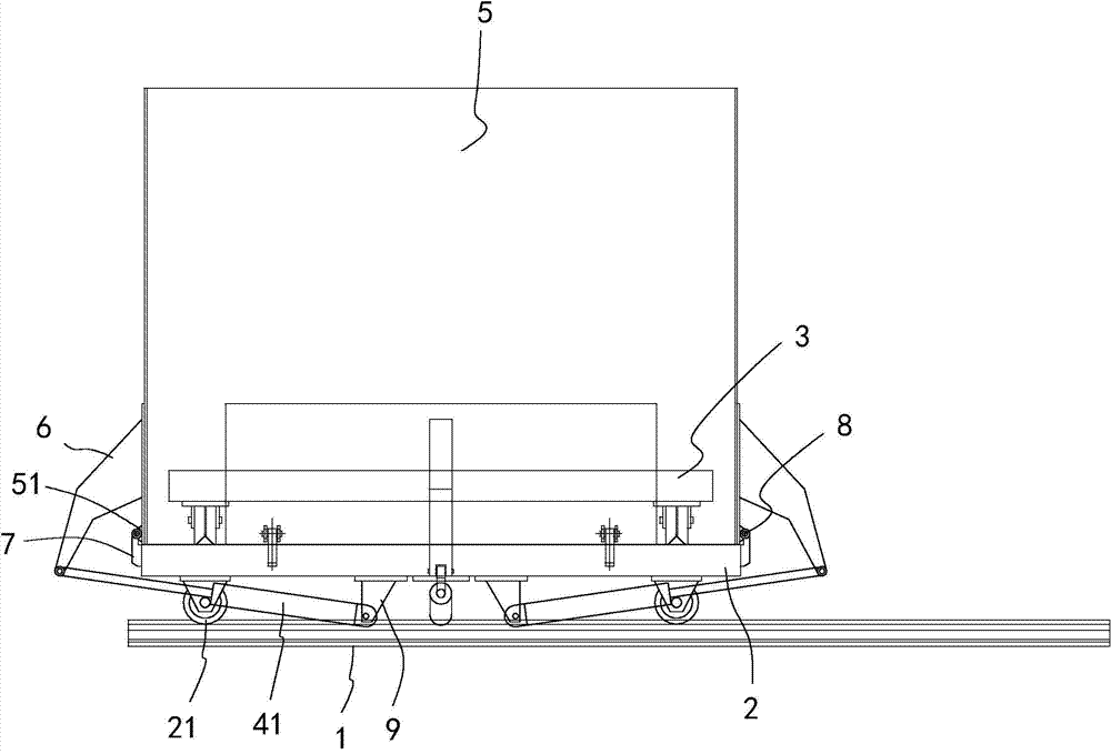
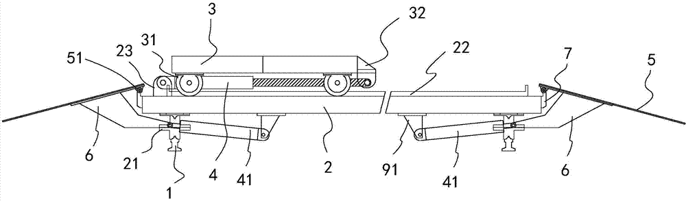
[0016] refer to Figure 1 to Figure 4 , the present embodiment discloses a mine car with a hydraulic feed and slicer for a stone sawing machine, which includes two transverse guide rails 1, a lower car body 2, an upper car body 3, four push plate oil cylinders 41, four coaming plates 5 and four pendulums. Arm 6, the two transverse guide rails 1 are arranged at intervals left and right, the lower vehicle body 2 is arranged above the two transverse guide rails 1 so as to be laterally slidable, and the lower longitudinal sides of the lower vehicle body 2 are respectively provided at intervals along each The transverse pulley 21 of free movement on the transverse guide rail 1, the upper lateral sides of the lower vehicle body 2 are respectively provided with longitudinal guide rails 22, and the upper vehicle body 3 can be longitudinally slidable and arranged on the longitudinal guide rails 22. Longitudinal pulleys 31 are arranged at intervals corresponding to the positions of the ...
PUM
 Abstract
Description
Claims
Application Information