Rainwater drainage system in factory

A drainage system and rainwater technology, which is applied to waterway systems, drainage structures, water/sewage treatment, etc., can solve the problems of huge investment in pump room civil engineering and equipment, low work efficiency, inconvenient installation and maintenance, and reduce civil engineering and equipment. The effect of less investment, less floor space, and less floor space for maintenance

Active Publication Date: 2014-10-29
SHANDONG HUANNENG DESIGN INST
View PDF5 Cites 7 Cited by
  • Summary
  • Abstract
  • Description
  • Claims
  • Application Information

AI Technical Summary

Problems solved by technology

The depth of the rainwater forebay and the pump room is generally below 11m underground, and the height above the ground of the pump room is more than 9m. The civil construction and equipment investment of the pum

Method used


Image

  • Rainwater drainage system in factory

Examples


Embodiment Construction

[0017] In order to better understand the present invention, the implementation manner of the present invention will be explained in detail below in conjunction with the accompanying drawings.

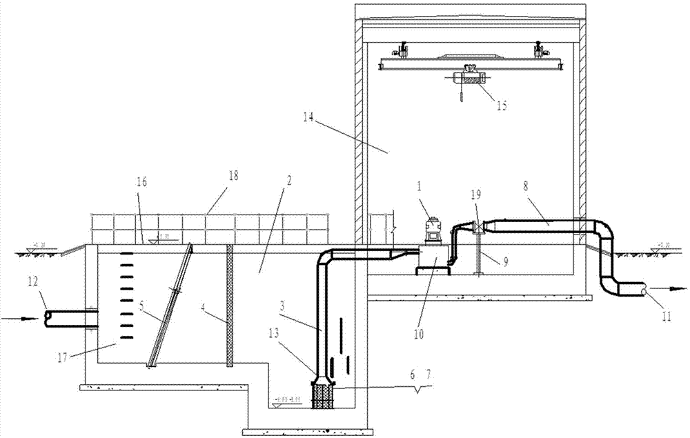
[0018] Such as figure 1 As shown, a rainwater drainage system in a factory area includes a connected rainwater pump body 10, a rainwater pump motor 1, and a rainwater pool 2. The rainwater pump body 10 is connected to the outlet pipe 8 through a switch valve 19, and the outlet pipe 8 is connected to the outlet pipe 8. The drainage pipe 11 is connected, the switch valve 19 is supported on the lower support surface by the bracket 9, the rainwater pool 2 is connected with the external rainwater incoming pipe 12, and the rainwater pump body 10 is connected with the outlet end of the water suction pipe 3, The water inlet end 13 of the water suction pipe is in the lower part of the rainwater pool 2, the water inlet end 13 is connected with the fixed bracket 6, the fixed bracket 6 is supported...


PUM


Abstract

The invention discloses a rainwater drainage system in a factory. The rainwater drainage system comprises a rainwater pump body, a rainwater pump motor and a rainwater tank, wherein the rainwater pump body, the rainwater pump motor and the rainwater tank are connected. The rainwater pump body is connected with a water outlet pipe through a switching valve, the water outlet pipe is connected with a water drainage pipeline, the switching valve is supported by a lower supporting face through a support, and the water outlet pipe is higher than a water outlet of the rainwater pump body and the water drainage pipeline. The rainwater tank is connected with an outer rainwater inflowing pipeline, the rainwater pump body is connected with the water outlet end of a water sucking pipe, and the water inlet end of the water sucking pipe is arranged on the lower portion of the rainwater tank and connected with a fixing support. The fixing support is supported by the lower ground surface, and a lead wire net is arranged on the periphery of the fixing support. The rainwater tank at the water inlet side is internally provided with a separation grid for separating large impurities such as suspended matter out. The rainwater drainage system in the factory is small in occupied area, capable of saving pump house civil engineering investment, convenient to install, maintain and overhaul, capable of reducing rainwater pump house civil engineering and equipment investment and capable of lowering the maintenance difficulty level of a rainwater pump.

Description

technical field [0001] The invention relates to the technical field of drainage equipment, in particular to a rainwater drainage system in factory areas, which is applied to rainwater drainage in thermal power plants, chemical plants and other factory areas. Background technique [0002] In the prior art, thermal power plants, chemical plants and other factories occupy more and more land. In order to meet the drainage requirements, the diameter and buried depth of rainwater pipes in the factory area are getting larger and larger, and usually the rainwater pump room needs to be installed in the factory area. In the prior art, vertical mixed-flow pumps are usually used for rainwater pumps. Because the impeller of the vertical mixed-flow pump has a wide water inlet channel, it can effectively prevent clogging, and is suitable for water sources such as rainwater with a lot of impurities in the water. The depth of the rainwater forebay and the pump room is generally below 11m und...

Claims


Application Information

Patent Timeline
IPC IPC(8): E03F1/00E03F5/10E03F5/14E03F5/22
Inventor 秦治虎王友梅
Owner SHANDONG HUANNENG DESIGN INST
Why Eureka
Try Eureka