Method, device and system for controlling diesel engine compression release brake

A technology for brake control and diesel engine, applied in engine control, electrical control, fuel injection control, etc., can solve problems such as cylinder wear and seriousness, and achieve the effect of improving reliability

Active Publication Date: 2017-03-08
WEICHAI POWER CO LTD
View PDF6 Cites 0 Cited by
  • Summary
  • Abstract
  • Description
  • Claims
  • Application Information

AI Technical Summary

Problems solved by technology

[0013] However, in the prior art, due to the unreasonable control of single-stage braking and double-stage braking, some cylinders are more severely worn.

Method used


Image

  • Method, device and system for controlling diesel engine compression release brake
  • Method, device and system for controlling diesel engine compression release brake
  • Method, device and system for controlling diesel engine compression release brake

Examples


Embodiment 1

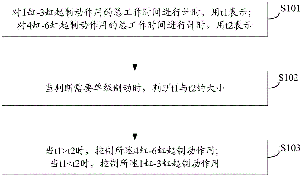
[0060] see figure 1 , which is a flow chart of Embodiment 1 of the diesel engine compression release braking control method provided by the present invention.

[0061] The diesel engine compression release braking control method provided in this embodiment includes the following steps:

[0062] S101: Timing the total working time of cylinder 1-3 for braking, expressed by t1; timing the total working time of cylinder 4-6 for braking, expressed by t2;

[0063] It should be noted that, in this embodiment, a diesel engine with 6 cylinders is used as an example for introduction. In the prior art, single-stage braking is 1-3 cylinders for braking, and double-stage braking is 1-6 cylinders. The cylinder acts as a brake. However, in the embodiment of the present invention, the working hours of cylinders 1-3 and cylinders 4-6 are timed respectively, and which group will work when the next single-stage braking is determined according to the working hours of the two groups of cylinders...

Embodiment 2

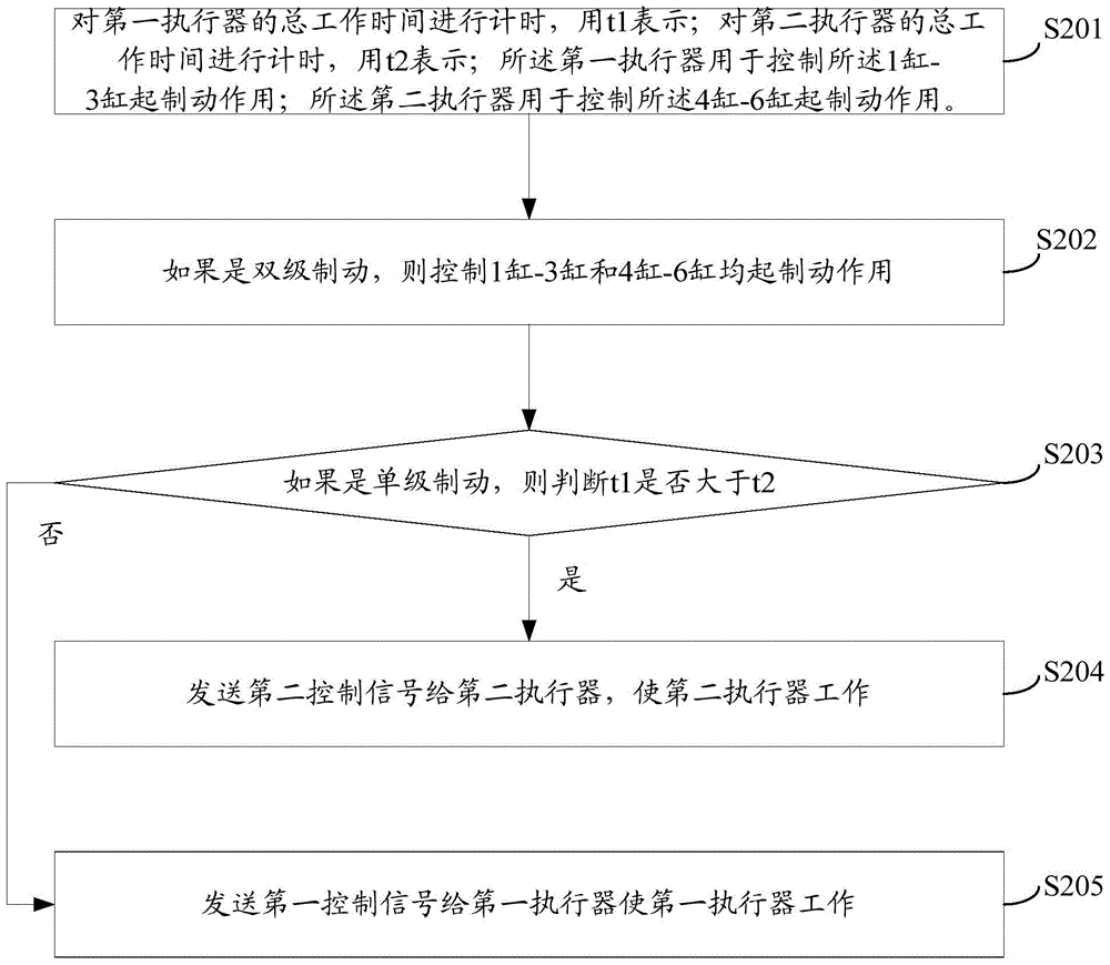
[0073] see figure 2 , which is a flow chart of Embodiment 2 of the diesel engine compression release braking control method provided by the present invention.

[0074] S201: Timing the total working time of the first actuator, represented by t1; timing the total working time of the second actuator, represented by t2; the first actuator is used to control the cylinder 1-3 Braking function; the second actuator is used to control the 4-6 cylinders to play a braking role.

[0075] It should be noted that since the first actuator is used to control cylinder 1-3 to perform braking work, the second actuator is used to control cylinder 4-6 to perform braking work. In fact, the first actuator and the second actuator are two solenoid valves, respectively the first solenoid valve and the second solenoid valve.

[0076] The opening and closing of the first solenoid valve and the second solenoid valve need to be controlled by the ECU sending a control signal. Therefore, when the ECU se...


PUM


Abstract

The invention provides a diesel engine compressing, releasing and braking control method, device and system. The method comprises the steps that the total braking working time of a first cylinder, a second cylinder and a third cylinder is counted and is represented with t1; the total braking working time of a fourth cylinder, a fifth cylinder and a sixth cylinder is counted and is represented with t2; when single-stage braking is needed, the relationship between t1 and t2 is judged; when t1 is larger than t2, the fourth cylinder, the fifth cylinder and the sixth cylinder are controlled to play a braking role; when t1 is smaller than t2, the first cylinder, the second cylinder and the third cylinder are controlled to play a braking role. The total working time of the first cylinder, the second cylinder and the third cylinder is compared with the total working time of the fourth cylinder, the fifth cylinder and the sixth cylinder to judge that during one-stage braking, the set of cylinders corresponding to the short total working time is used for playing the role of braking, and the two sets of cylinders can play the role of braking alternately. According to the control method, the two sets of cylinders can be utilized in a balanced mode, and the situation that one set of cylinders are used frequently while the other set of cylinders are used less cannot occur. Thus, working reliability of a whole diesel engine can be improved.

Description

technical field [0001] The invention relates to the technical field of engine control, in particular to a diesel engine compression release braking control method, device and system. Background technique [0002] The braking principle of diesel engine (referred to as diesel engine) is introduced as follows: [0003] When the vehicle is running, the diesel engine stops supplying fuel, and the transmission is put into a certain forward gear, so that the vehicle drives the crankshaft of the diesel engine to continue to rotate through the drive wheel and transmission system. In this way, when the brake is activated and under the action of the brake, the diesel engine becomes an air compressor that consumes the kinetic energy of the vehicle to slow down the speed of the vehicle, or the diesel engine does negative work at this time. [0004] In this case, most of the work input by the vehicle to the diesel engine is consumed in the process of air intake, compression, and exhaust ...

Claims


Application Information

Patent Timeline
Patent Type & Authority Patents(China)
IPC IPC(8): F02D41/00F02D29/02
Inventor 李文广翟长辉
Owner WEICHAI POWER CO LTD
Why Eureka
Try Eureka