Vapor chamber vacuum sealing structure and making method thereof

A technology of uniform temperature plate and vacuum pressing, applied in lighting and heating equipment, indirect heat exchangers, etc., can solve the problems of complex manufacturing process, influence of ideal shape, and unenvironmental protection of solder pollution.

Inactive Publication Date: 2014-10-29
SUZHOU FORCECON ELECTRIC
View PDF5 Cites 7 Cited by
  • Summary
  • Abstract
  • Description
  • Claims
  • Application Information

AI Technical Summary

Problems solved by technology

[0003] The disadvantage is that the structural shape and molding method of the above-mentioned existing temperature chambers still have some problems and disadvantages in practical application experience. The reason is that the gap is usually punched out of the three-dimensional cover by using the upper cover plate. The shape of the shell is formed by punching out a half-pipe shape around its periphery. After being stacked and combined with the lower cover plate, a gap with an opening facing the side is formed. However, the design of the gap does not conform to the shape of the side ope

Method used


Image

  • Vapor chamber vacuum sealing structure and making method thereof
  • Vapor chamber vacuum sealing structure and making method thereof
  • Vapor chamber vacuum sealing structure and making method thereof

Examples


Embodiment

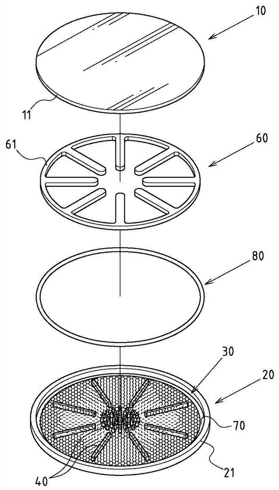
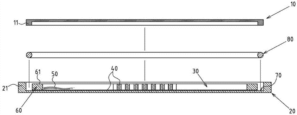
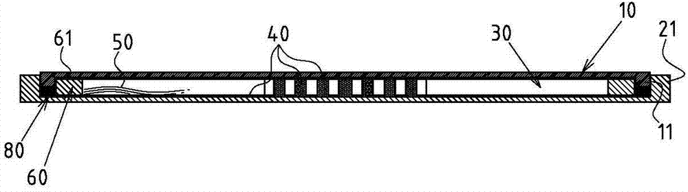
[0042] Embodiment: Please refer to Figures 1 to 5, which are preferred embodiments of the vacuum sealing structure of the chamber and its manufacturing method of the present invention. These embodiments are for illustration purposes only and are not subject to patent application. The limitations of this structure: the vapor chamber is formed by stacking an upper cover plate 10 and a lower cover plate 20, and a vacuum-enclosed hollow chamber 30 is formed inside the upper cover plate 10 and the lower cover plate 20 , the hollow chamber 30 is provided with capillary tissue 40 and working fluid 50 (please refer to image 3 , 5shown); wherein, the upper cover 10 is provided with an upper sealing ring 11, and the lower cover 20 is provided with a lower sealing ring 21; the inner side of the lower sealing ring 21 is also provided with an inner The ring frame 60, the inner ring frame 60 and the inner side of the lower sealing ring 21 are relatively defined to form an annular slot 70 ...


PUM


Abstract

A vapor chamber vacuum sealing structure and a making method thereof; the vapor chamber is formed by stacking an upper cover plate and a lower cover plate; a vacuum sealing hollow cavity is formed between the upper cover and the lower cover; an upper cover periphery is provided with an upper sealing ring, and a lower cover plate periphery is matched with a lower sealing ring; an inner ring rack is arranged in an inner side of the lower sealing ring; an annular nested slot is formed between the inner ring rack and the lower sealing ring inner side so as to allow the upper sealing ring of the upper cover to fit in; a top of the inner ring rack is provided with a limit surface; the annular nested slot is assembled with an elastic stop sealing ring; when the upper sealing ring is nested in the annular nested slot, the elastic stop sealing ring is pressed to deform and expand so as to combine with the annular nested slot, so a vacuum state of the hollow cavity can be kept; the limit surface on the top of the inner ring rack can press against the upper cover plate so as to limit a maximum depth of the sealing ring nesting in the annular nested slot; the vapor chamber vacuum sealing structure can simplify making steps and reduce making cost.

Description

technical field [0001] The invention relates to a vapor chamber product, in particular to an innovative form and a manufacturing method of a vacuum sealing structure of a chamber. Background technique [0002] The structural form of the existing temperature chamber is usually composed of an upper cover plate and a lower cover plate stacked together and combined and fixed by the periphery of the two; and the periphery of the upper cover plate and the lower cover plate is completed. After the fixing step is combined, usually a gap must be reserved for subsequent steps such as vacuuming and liquid injection inside the chamber, and then the gap is closed by soldering. [0003] The disadvantage is that the structural shape and molding method of the above-mentioned existing temperature chambers still have some problems and disadvantages in practical application experience. The reason is that the gap is usually punched out of the three-dimensional cover by using the upper cover pla...

Claims


Application Information

Patent Timeline
IPC IPC(8): F28D15/04
Inventor 饶振奇何信威黄志仁
Owner SUZHOU FORCECON ELECTRIC
Why Eureka
Try Eureka