

Method and device for measuring modulation transfer functions of optic lenses through infinite conjugated light paths
A modulation transfer function, optical lens technology, applied in the direction of testing optical performance, etc., can solve the problem of large lens error, and achieve the effect of meeting the testing requirements, easy to popularize and apply, and convenient for users to operate
- Summary
- Abstract
- Description
- Claims
- Application Information
AI Technical Summary
Problems solved by technology
Method used
Image


Examples
Embodiment Construction
[0044] The content of the present invention will be described in detail below in conjunction with the accompanying drawings and specific embodiments of the description:
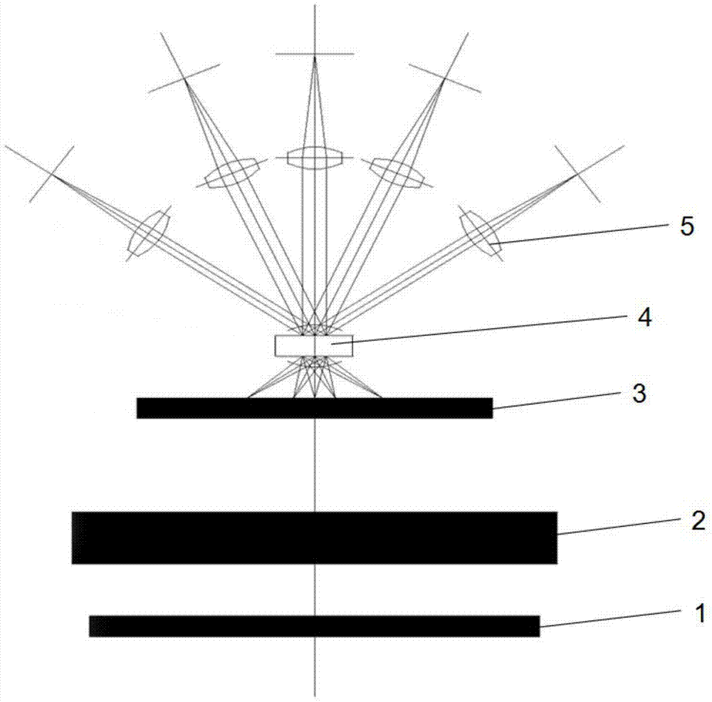
[0045] Such as figure 1 As shown, the optical path diagram of the modulation transfer function method of the infinite conjugate optical path measurement optical lens provided by the present invention, the method comprises the following steps:
[0046] ①Distribute a plurality of digital cameras 5 on the object side of the tested lens 4 according to the measurement requirements of the tested lens 4, and the angle between each digital camera 5 and the optical axis of the tested lens 4 is less than or equal to the maximum field of view of the tested lens 4 half of the angle, and make the optical axis of each digital camera 5 align with the principal point of the object space of the lens under test 4, each digital camera 5 is preferably arranged on the optical axis of the lens under test 4 and / or around the optica...
PUM
 Abstract
Description
Claims
Application Information