
Thermomagnetic power generation system driven by linear compressor

A technology for linear compressors and power generation systems, which is applied to thermoelectric devices utilizing thermal changes in magnetic permeability, etc., can solve problems such as limited high temperature, complicated installation of piston pumps and flow channel seals, and restrictions on the application of high Curie point soft magnetic materials. , to achieve the effect of quiet operation, simple installation, safe and stable use

Active Publication Date: 2014-10-29
TECHNICAL INST OF PHYSICS & CHEMISTRY - CHINESE ACAD OF SCI
View PDF4 Cites 5 Cited by
  • Summary
  • Abstract
  • Description
  • Claims
  • Application Information

AI Technical Summary

Problems solved by technology

However, the sealing installation of the piston pump and the flow channel is more complicated. At the same time, the high-temperature heat exchanger needs a heating rod to supply energy. First, the high temperature provided is limited, which limits the application of soft magnetic materials with a high Curie point; second, the heating rod is also an input of electric energy. There are constraints on the calculation of efficiency and the application of thermomagnetic power generation technology

Method used


Image

  • Thermomagnetic power generation system driven by linear compressor
  • Thermomagnetic power generation system driven by linear compressor
  • Thermomagnetic power generation system driven by linear compressor

Examples


Embodiment 1

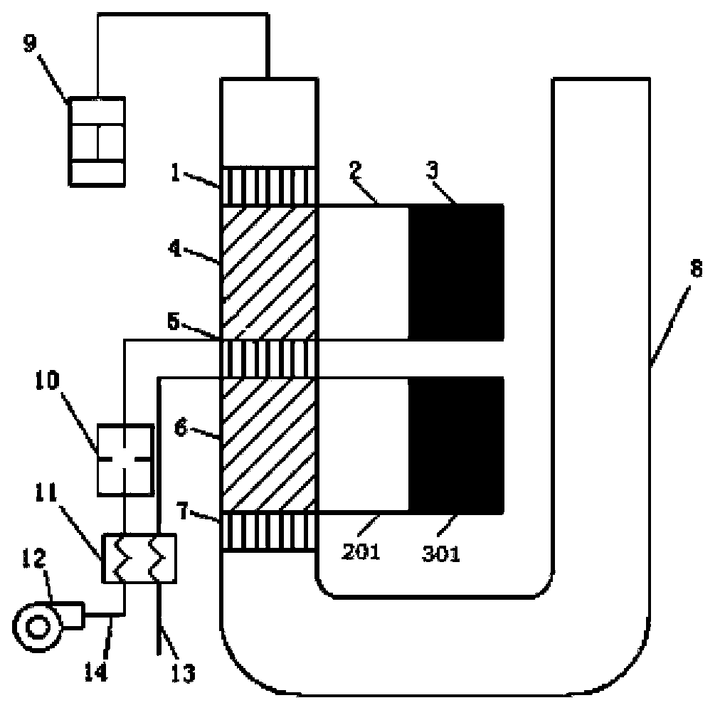
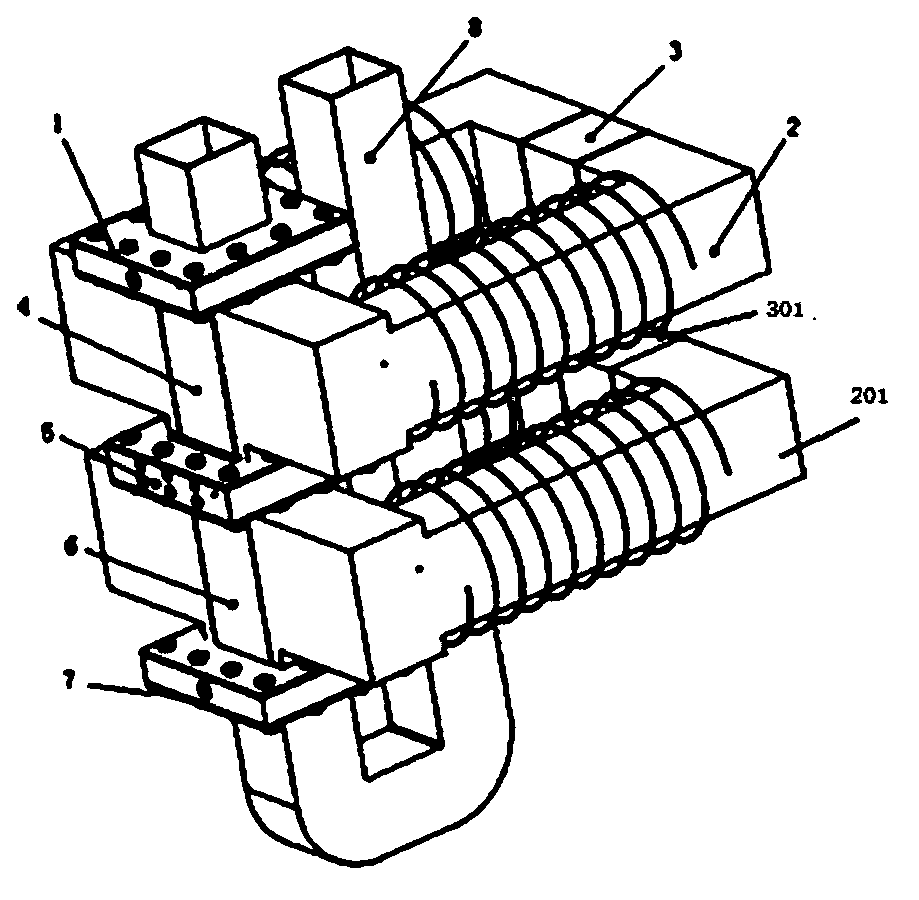
[0049] Picture 1-1 It is a schematic structural diagram of a thermomagnetic power generation system (embodiment 1) driven by a linear compressor of the present invention.

[0050] Figure 1-2 for Picture 1-1 As can be seen from the figure, the thermomagnetic power generation system driven by the linear compressor of the present embodiment 1; the heat source supply system provides the required heat for the high temperature heat exchanger of the thermomagnetic generator; the thermomagnetic generator utilizes fluid The alternating flow converts the thermal energy of the high temperature heat exchanger into electrical energy;

[0051] Thermomagnetic generators include:

[0052] A heat exchange assembly composed of the first room temperature heat exchanger 1, the first soft magnetic body 4, the high temperature heat exchanger 5, the second soft magnetic body 6 and the second room temperature heat exchanger 7 connected in sequence;

[0053] A pair of bow-shaped upper magnetize...

Embodiment 2

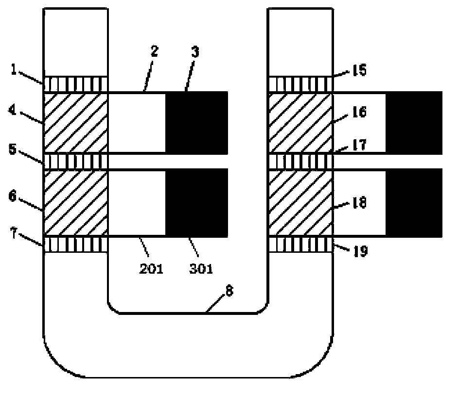
[0066] figure 2 It is a schematic structural diagram of a thermomagnetic power generation system (Example 2) driven by a linear compressor of the present invention.

[0067] In order to improve efficiency and make full use of the fluid reciprocating motion provided by the linear compressor, a symmetrical arrangement is designed on the right side of the U-shaped flow channel 8 and the left side. composition. When the fluid flows counterclockwise, it first cools down through the first room temperature heat exchanger 1, then cools the first soft magnetic body 4, then heats up in the first high temperature heat exchanger 5, then heats the second soft magnetic body 6, and then cools down by the second room temperature The heat exchanger 7 cools down, and in the flow channel on the right, the fourth room temperature heat exchanger 19 cools down first, then cools the fourth soft magnetic body 18, then heats up by the second high temperature heat exchanger 17, heats the third soft m...

Embodiment 3

[0069] image 3 It is a schematic structural diagram of a thermomagnetic power generation system (embodiment 3) driven by a linear compressor of the present invention.

[0070]In this example, the soft magnets in the left and right channels are divided into several sections according to the height of the Curie point, and the left and right symmetrical soft magnets are connected in a magnetic circuit, so that when the fluid reciprocates, the symmetrical soft magnets are simultaneously Heating and cooling causes a greater amount of flux change in the magnetic circuit, resulting in a greater current flow. Due to the limited amplitude of fluid oscillation, and the heat transfer fluid is heat transfer oil with a relatively small heat penetration depth, it is difficult for the soft magnet to fully exchange heat. In this example, the soft magnet is divided into several sections according to the Curie point, which can ensure Within the oscillation amplitude of the fluid, there is eno...


PUM


Abstract

A thermomagnetic power generation system driven by a linear compressor comprises the linear compressor, a heat source supply system and a thermomagnetic power generator. The heat source supply system supplies heat for the thermomagnetic power generator; and the thermomagnetic power generator utilizes alternating flow of fluid to converts the heat into electric energy. The thermomagnetic power generator comprises two room temperature heat exchangers; a high temperature heat exchanger arranged between the two room temperature heat exchangers; soft magnets arranged between the room temperature heat exchangers and the high temperature heat exchanger; and two groups of oppositely-arranged bow-type magnetizers. One end of each group of bow-type magnetizer is clamped with a permanent magnet, and the other end is clamped with a soft magnet. The magnetizers are respectively provided with a coil. Each soft magnet, the permanent magnet and a group of bow-type magnetizer form a magnetic loop. When working, the linear compressor drives the fluid to move back and forth between the room temperature heat exchangers and the high temperature heat exchanger, so that the soft magnets are heated and cooled periodically, the temperature changes around the curie point, the magnetic conductivity changes periodically, the magnetic loop reluctance and magnetic flux change, and the coils generate induced electromotive force to generate electric energy. The thermomagnetic power generation system is noiselessness, wide in applied temperature range and flexible in generated energy adjusting.

Description

technical field [0001] The invention relates to a thermomagnetic power generation device, in particular to a thermomagnetic power generation system driven by a linear compressor. Background technique [0002] The thermomagnetic generator is a device that uses a high-permeability soft magnetic material to undergo a huge change in the permeability near the Curie point, thereby causing a change in the magnetic flux passing through the coil in the magnetic circuit, and then generating electrical energy. However, thermomagnetic power generation systems need to alternately heat and cool magnetic materials, and how to achieve rapid heating and cooling of magnetic materials is one of the difficulties in this technology. [0003] Thermomagnetic power generation systems driven by reciprocating piston pumps in the prior art, such as Figure 8 As shown, 1 is the first room temperature heat exchanger, 4 is a soft magnetic body stacked with soft magnetic material sheets, 5 is a high tempe...

Claims


Application Information

Patent Timeline
Patent Type & Authority Applications(China)
IPC IPC(8): H01L37/04H10N15/20
Inventor 罗二仓李东辉吴张华
Owner TECHNICAL INST OF PHYSICS & CHEMISTRY - CHINESE ACAD OF SCI
Learn More