Manufacturing method of plate coiling hollow drum, plate coiling hollow drum and steel plate manufacturing process device

A manufacturing method and coiling technology, which are applied in the manufacture of hollow coiling drums, hollow coiling drums, and steel plate manufacturing process devices, and can solve problems such as inability to fully utilize the production capacity of equipment, meandering or slipping of steel plates, and low tension of steel plates , to achieve the effect of easy application of laser welding, ensuring butt joint accuracy and high butt joint accuracy

Active Publication Date: 2016-09-28
PRIMETALS TECHNOLOGIES JAPAN LTD
View PDF10 Cites 0 Cited by
  • Summary
  • Abstract
  • Description
  • Claims
  • Application Information

AI Technical Summary

Problems solved by technology

In particular, in high-grade surface-treated steel sheets such as galvanized, this transfer appears clearly and becomes a cause of product failure.
[0010] In addition, in order to avoid the transfer of the weld line, the tension of the steel sheet tends to be set low, which also causes the steel sheet to meander or slip.
In other words, the production capacity of the equipment cannot be fully utilized, resulting in a problem of reduced yield

Method used


Image

  • Manufacturing method of plate coiling hollow drum, plate coiling hollow drum and steel plate manufacturing process device
  • Manufacturing method of plate coiling hollow drum, plate coiling hollow drum and steel plate manufacturing process device
  • Manufacturing method of plate coiling hollow drum, plate coiling hollow drum and steel plate manufacturing process device

Examples


no. 1 Embodiment >

[0064] use Figure 1 to Figure 5 The first embodiment of the manufacturing method of the board bending hollow roll of this invention is demonstrated.

[0065] First, coiling is performed by bending a rectangular metal plate into a cylindrical shape.

[0066] As the metal plate, other than carbon steel, stainless steel, chromium steel enhanced in hardenability or wear resistance, or chrome-molybdenum steel can be used.

[0067] In addition, the method of coiling processing should just be a well-known method.

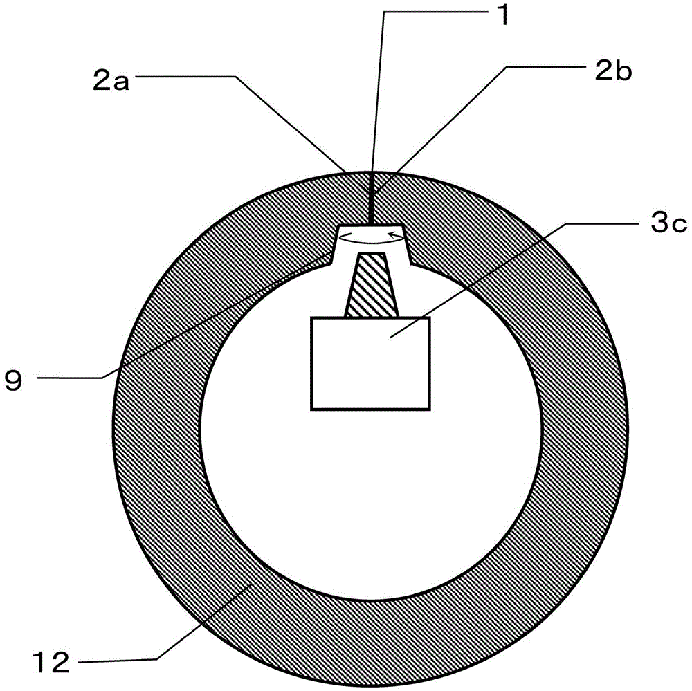
[0068] Next, the butt left end surface 2a and the butt right end surface 2b of the cylindrical metal plate 12 subjected to the coiling process are spot-welded to the butt portion 1 of the metal plate 12, preferably to the side of the butt portion 1. Welding is temporarily fixed so that it becomes a butt joint state.

[0069] Then, if figure 1 As shown, the inner peripheral surfaces of the butt left end surface 2a and the butt right end surface 2b after temporarily fix...

no. 2 Embodiment >

[0107] use Image 6 and Figure 7 The second embodiment of the manufacturing method of the board bending hollow roll of this invention is demonstrated.

[0108] First, in the same manner as in Example 1, a plate bending process of bending a rectangular metal plate into a cylindrical shape was performed. Then, spot welding or the like is performed on the butt portion 1 of the cylindrical metal plate 12 , preferably on the side surface of the butt portion 1 , to temporarily fix and weld it, thereby bringing it into a butt state.

[0109] Next, if figure 1 As shown, beveling is performed on the inner peripheral surface side of the butt part 1 after provisional fixing welding by a machining device 3 c having an end mill or the like.

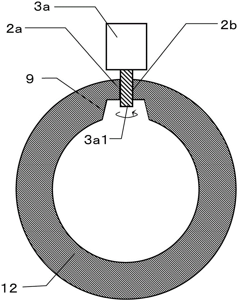
[0110] Then, use Image 6 A machining device 3b having a tapered end mill 3b1 as shown performs butting processing on the mating portion 1 of the metal plate 12 to form tapered gaps at intervals of about 10 mm.

[0111] Here, for example as Fi...

no. 3 Embodiment >

[0124] use Figure 8 The third embodiment of the manufacturing method of the board bending hollow roll of this invention is demonstrated.

[0125] Figure 8 It is an explanatory diagram of the laser welding process performed by an arm robot.

[0126] First, in the same manner as in Example 1 and the like, a plate bending process of bending a rectangular metal plate into a cylindrical shape was performed. Then, spot welding or the like is performed on the butt portion 1 of the cylindrical metal plate 12 , preferably on the side surface of the butt portion 1 , to temporarily fix and weld it, thereby bringing it into a butt state.

[0127] Next, if figure 1 As shown, beveling is performed on the inner peripheral surface side of the butt part 1 after provisional fixing welding by a machining device 3 c having an end mill or the like.

[0128] And, using a machining device having a linear end mill 3a1 or a tapered end mill 3b1, the mating portion 1 of the metal plate 12 is subj...


PUM

PropertyMeasurementUnit
diameteraaaaaaaaaa

Abstract

Carry out coiling, which bends a metal plate into a cylindrical shape. Next, spot welding or the like is performed on the side surface of the butt portion (1) to temporarily fix and weld the butt left end surface (2a) and the butt right end surface (2b) of the metal plate (12). Then, grooves are provided on the inner peripheral sides of the butted ends. Next, a mating process is performed on the mating portion (1) to uniformly form a space between both end surfaces. Next, the outer peripheral surface of the mated metal plate (12) is pressed by the pressing bolt equipped on the C-shaped fixing jig (7), and the state where the gap is narrowed is maintained. Then, the butt joint (1) is laser welded by a laser welding device (6a). Furthermore, the metal plate (12) bent into a cylindrical shape is formed into a cylindrical shape by joining the abutting portions (1) by high heat input welding using a welding material. As a result, it is possible to efficiently and cost-effectively manufacture hollow plate bending rolls that can achieve high surface quality while eliminating the transfer of the surface shape of the roll to the steel sheet to be conveyed while the production capacity of the equipment is fully utilized. The transportation of the steel plate.

Description

technical field [0001] The present invention relates to a manufacturing method of a plate coiling hollow drum, a plate coiling hollow drum, and a steel plate manufacturing process device, capable of conveying a steel plate while maintaining a higher surface quality of the steel plate in a steel plate conveying process of the steel plate manufacturing process, and reducing the weight of the hollow drum. manufacturing cost. Background technique [0002] In the steel sheet manufacturing process, a large number of transfer rollers are used to transfer the steel sheet. [0003] Among them, for the relatively large-diameter rollers, for the purpose of cost reduction, more hollow rollers are used instead of solid rollers, wherein the hollow rollers bend and weld plates to form a cylindrical shape. [0004] With the demand for advanced steel sheet surface quality, it is necessary to transfer the steel sheet in a state where the surface quality of the steel sheet is maintained highe...

Claims


Application Information

Patent Timeline
Patent Type & Authority Patents(China)
IPC IPC(8): B23K26/00B23P23/02
CPCB23K33/006B21C37/08B23K26/0884B23K26/10B23K26/262B23K26/32B23K37/0229B23K37/0533B23K2101/06B23K2103/04B23K2103/50
Inventor 池田博之末盛秀昭甲斐洋一吉尾史朗橘高和久山口孝幸会田孝幸藤原裕太星本达也
Owner PRIMETALS TECHNOLOGIES JAPAN LTD
Why Eureka
Try Eureka