Manufacturing method of plate coiling hollow drum, plate coiling hollow drum and steel plate manufacturing process device

A manufacturing method and coiling technology, used in manufacturing tools, metal rolling, metal rolling, etc., can solve the problems of low steel plate tension, unqualified products, and reduced yield, and achieve improved docking accuracy, elimination of transfer printing, The effect of improving the tightness

Active Publication Date: 2017-03-15
PRIMETALS TECHNOLOGIES JAPAN LTD
View PDF7 Cites 0 Cited by
  • Summary
  • Abstract
  • Description
  • Claims
  • Application Information

AI Technical Summary

Problems solved by technology

In particular, in high-grade surface-treated steel sheets such as galvanized, this transfer appears clearly and becomes a cause of product failure.
[0010] In addition, in order to avoid the transfer of the weld line, there is a tendency to set the tension of the steel plate low, which also causes the steel plate to snake or slip.
In other words, the production capacity of the equipment cannot be fully utilized, resulting in a problem of reduced yield

Method used


Image

  • Manufacturing method of plate coiling hollow drum, plate coiling hollow drum and steel plate manufacturing process device
  • Manufacturing method of plate coiling hollow drum, plate coiling hollow drum and steel plate manufacturing process device
  • Manufacturing method of plate coiling hollow drum, plate coiling hollow drum and steel plate manufacturing process device

Examples


no. 1 Embodiment

[0054] use Figure 1 to Figure 4 The first embodiment of the manufacturing method of the board bending hollow roll of this invention is demonstrated.

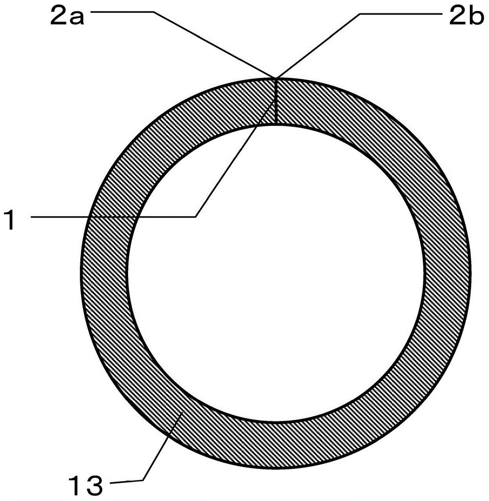
[0055] figure 1 It is a figure which shows the state of the board bending hollow roll in Example 1 after welding.

[0056] Such as figure 1 As shown, the plate rolling hollow cylinder is a cylindrical metal plate 13, and the butt left end surface 2a and the butt right end surface 2b of the metal plate 12 processed into a cylindrical shape by rolling are placed at the butt joint 1 so that no welding material is interposed It is joined by laser welding.

[0057] Next, the manufacturing method of the board bending hollow roll of this invention is demonstrated.

[0058] First, coiling is performed by bending a rectangular metal plate into a cylindrical shape.

[0059] As the metal plate, other than carbon steel, stainless steel, chromium steel enhanced in hardenability or wear resistance, or chrome-molybdenum steel can be used...

no. 2 Embodiment >

[0095] use Figure 5 and Image 6 The second embodiment of the manufacturing method of the board bending hollow roll of this invention is demonstrated.

[0096] First, in the same manner as in Example 1, a plate bending process of bending a rectangular metal plate into a cylindrical shape was performed. Then, spot welding or the like is performed on the butt portion 1 of the cylindrical metal plate 12 , preferably on the side surface of the butt portion 1 , to temporarily fix and weld it, thereby bringing it into a butt state.

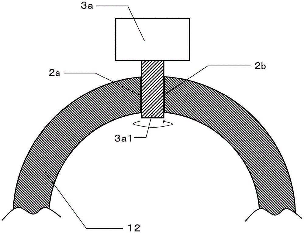
[0097] Next, use Figure 5 A machining device 3b having a tapered end mill 3b1 as shown performs butting processing on the mating portion 1 of the metal plate 12 to form tapered gaps at intervals of about 10 mm.

[0098] Here, for example as Image 6 As shown, the angle θ of the taper is based on the angle when radially opening toward the both end surfaces (2a, 2b) of the metal plate 12 with the point 8 as a reference, wherein the point 8 is relati...

no. 3 Embodiment >

[0110] use Figure 7 The third embodiment of the manufacturing method of the board bending hollow roll of this invention is demonstrated.

[0111] Figure 7 It is an explanatory diagram of the laser welding process performed by an arm robot.

[0112] First, in the same manner as in Example 1 and the like, a plate bending process of bending a rectangular metal plate into a cylindrical shape was performed. Then, spot welding or the like is performed on the butt portion 1 of the cylindrical metal plate 12 , preferably on the side surface of the butt portion 1 , to temporarily fix and weld it, thereby bringing it into a butt state. Then, using a machining device having a linear end mill 3a1 or a tapered end mill 3b1, the mating portion 1 of the metal plate 12 is butted to form uniform or tapered gaps at intervals of about 10 mm.

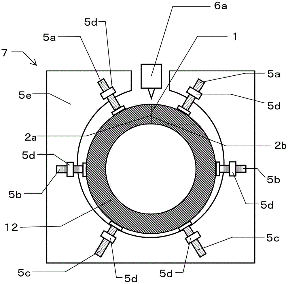
[0113] Then, in the same manner as in Example 1, etc., using equipment in image 3 C-fix clamps as shown 7 or Figure 4 The push bolts (5a, 5b, 5c)...


PUM

PropertyMeasurementUnit
diameteraaaaaaaaaa

Abstract

In the present invention, plate-bending processing in which a metal plate is bent into a cylindrical shape is performed. A butting left end surface (2a) and a butting right end surface (2b) of the metal plate (12) are subsequently tack welded by subjecting, to spot welding or the like, a side surface of a butt section (1). Thereafter, an end mill is used to subject the butt section (1) to joint processing, and an interval between the end surfaces is uniformly formed. The outer peripheral surface of the metal plate (12) which has been subjected to joint processing is then pressed by pressing bolts provided to a C-shaped fixation jig (7), to hold a gap in a reduced state. Thereafter, a laser beam welding device (6a) is used to perform laser beam welding on the butt section (1), and, as a result, the butt section (1) is joined, and the metal plate (12) bent into the cylindrical shape is formed into the cylindrical shape. Accordingly, a plate-bending hollow roll can be efficiently produced at low cost, while exhibiting a sufficient facility production capacity, said plate-bending hollow roll enabling the conveyance of steel plate with high surface quality, without having to imprint a roll-surface shape onto the steel plate to be conveyed.

Description

technical field [0001] The present invention relates to a manufacturing method of a plate coiling hollow drum, a plate coiling hollow drum, and a steel plate manufacturing process device, capable of conveying a steel plate while maintaining a higher surface quality of the steel plate in a steel plate conveying process of the steel plate manufacturing process, and reducing the weight of the hollow drum. manufacturing cost. Background technique [0002] In the steel sheet manufacturing process, a large number of transfer rollers are used to transfer the steel sheet. [0003] Among them, for the relatively large-diameter rollers, for the purpose of cost reduction, more hollow rollers are used instead of solid rollers, wherein the hollow rollers bend and weld plates to form a cylindrical shape. [0004] With the demand for advanced steel sheet surface quality, it is necessary to transfer the steel sheet in a state where the surface quality of the steel sheet is maintained highe...

Claims


Application Information

Patent Timeline
Patent Type & Authority Patents(China)
IPC IPC(8): B21B27/00B21C37/08B23K26/21
CPCB21C37/08B23K26/262
Inventor 池田博之末盛秀昭甲斐洋一吉尾史朗橘高和久山口孝幸会田孝幸藤原裕太星本达也
Owner PRIMETALS TECHNOLOGIES JAPAN LTD
Why Eureka
Try Eureka