Finisher nozzle and finisher assembly including the same
A technology for finishers and nozzles, applied in the field of finisher nozzles and finisher components including said finisher nozzles, capable of solving problems such as deterioration, expensive labor, and density
- Summary
- Abstract
- Description
- Claims
- Application Information
AI Technical Summary
Problems solved by technology
Method used
Image
Examples
Embodiment 1
[0058] Example 1 - Finisher assembly having a finisher nozzle with a tapered barrel.
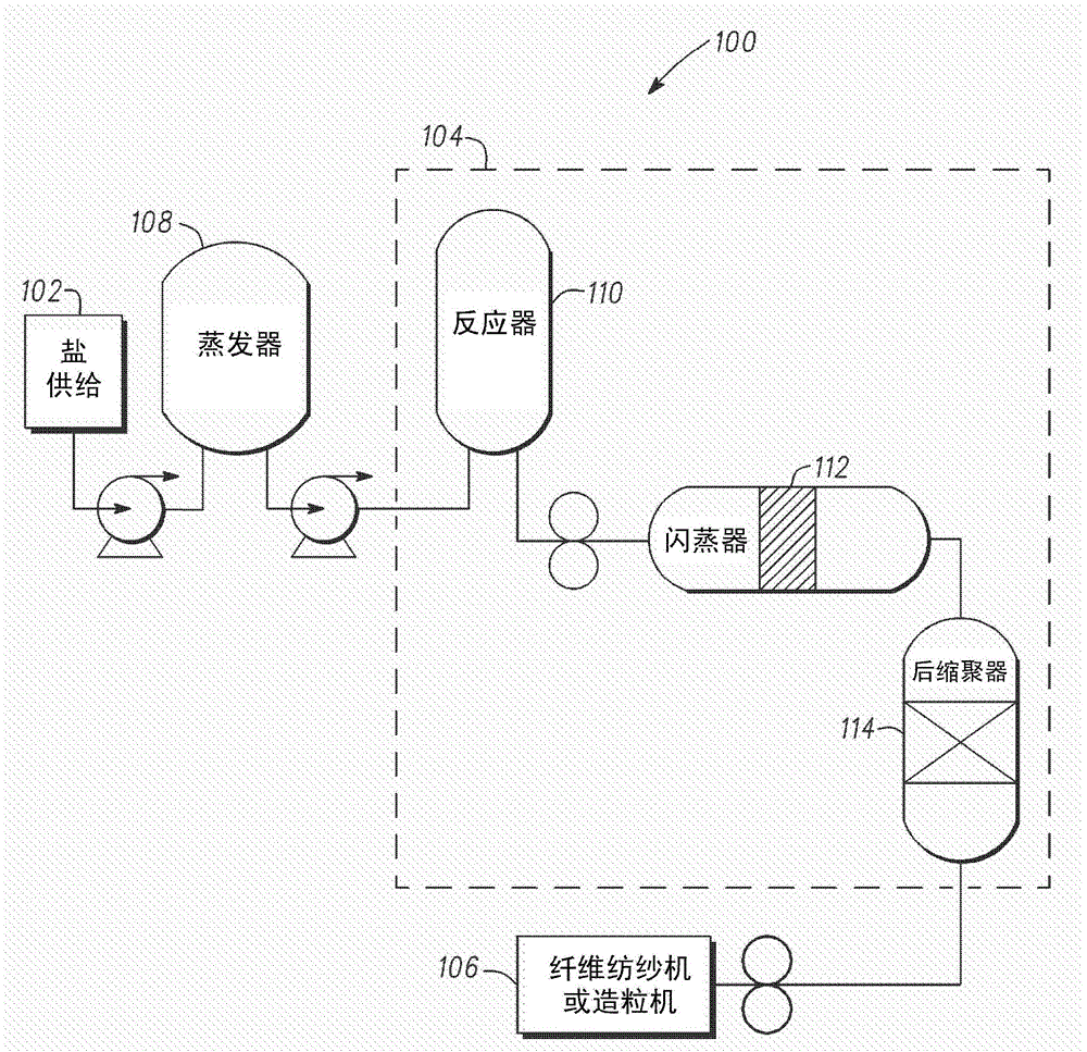
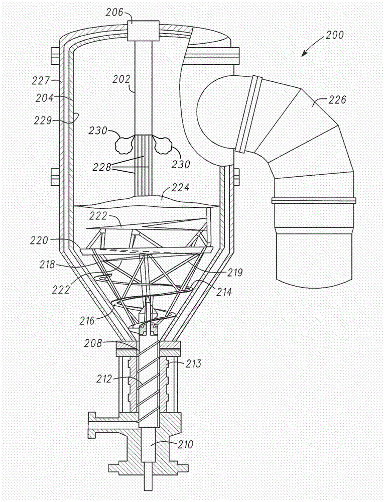
[0059] In a continuous nylon 6,6 manufacturing process, adipic acid and hexamethylenediamine are mixed in approximately equimolar ratios in water in a salt bath to form an aqueous mixture containing nylon 6,6 salt with about 50% water by weight . The brine solution was delivered to the evaporator at about 105 L / min. The evaporator heats the brine solution to about 125-135°C (130°C) and removes water from the heated brine solution such that the water concentration reaches about 30% by weight. The evaporated salt mixture was delivered to the reactor at about 75 L / min. The reactor brings the evaporated salt mixture to a temperature of about 218-250°C (235°C), thereby allowing the reactor to further remove water from the heated evaporated salt mixture, bring the water concentration to about 10% by weight, and allow the salt to further polymerization. The reacted mixture was transferred to ...
Embodiment 2
[0063] Example 2 - Finisher Assembly with Finisher Nozzle with Constant Inner Perimeter Barrel.
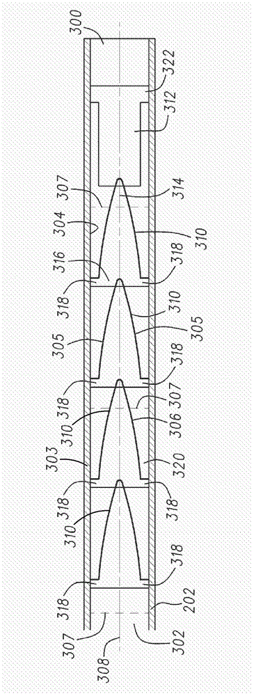
[0064] The continuous nylon 6,6 manufacturing process of Example 1 was carried out, but using a finisher nozzle, which was 5 m long and had a cylindrical barrel with a constant barrel inner circumference of 0.3 m between the nozzle inlet port and the nozzle outlet port, to Such that the entire length of the opposing walls of the cylindrical barrel between the nozzle inlet port and the nozzle outlet port form an angle of 0 degrees between each other. A separator spirals within the finisher nozzle and is spaced from the constant barrel inner perimeter. The finisher nozzle separates water vapor from the polymer fluid as it is delivered to the melt pool within the finisher vessel. The finisher vessel was inspected after 10 days of operation. There is evidence of reduced splashing of polymer fluid along the inner vessel wall of the finisher vessel on the shoreline of the melt pool ...
Embodiment 3
[0068] Example 3 - Finisher Nozzle with Separator Helix Connected Along the Inner Perimeter of the Barrel at a First Frequency cleanliness.
[0069] The continuous nylon 6,6 manufacturing process of Example 1 was carried out, but using a finisher nozzle with a finisher nozzle separator helix having 10 helical segments along the A line extending along the inside of the barrel and parallel to the axis of the helix is spot welded to the inner periphery of the barrel. The finisher nozzle, including the separator helix and each helix segment, was heated to a cleaning temperature of 350°C during the cleaning process. Inspection of the separator helix revealed warping of the helix segments and separator helix such that each segment not spot welded to the barrel was out of alignment with the original axis of the helix by 0.5-3 degrees.
PUM
| Property | Measurement | Unit |
|---|---|---|
| diameter | aaaaa | aaaaa |
| diameter | aaaaa | aaaaa |
Abstract
Description
Claims
Application Information
 - R&D
- Intellectual Property
- Life Sciences
- Materials
- Tech Scout
- Unparalleled Data Quality
- Higher Quality Content
- 60% Fewer Hallucinations
Browse by: Latest US Patents, China's latest patents, Technical Efficacy Thesaurus, Application Domain, Technology Topic, Popular Technical Reports.
© 2025 PatSnap. All rights reserved.Legal|Privacy policy|Modern Slavery Act Transparency Statement|Sitemap|About US| Contact US: help@patsnap.com


