Intra-system temperature-controlled algae liquid external circulating microalgae photobioreactor

A photobioreactor, external circulation technology, applied in photobioreactor, bioreactor/fermenter combination, specific-purpose bioreactor/fermenter, etc., can solve water waste, carbon dioxide waste, culture intrusion. to avoid carbon dioxide waste, improve efficiency and quality, and reduce adherence and precipitation

Inactive Publication Date: 2014-11-05
陈勇
View PDF6 Cites 4 Cited by
  • Summary
  • Abstract
  • Description
  • Claims
  • Application Information

AI Technical Summary

Problems solved by technology

[0006] The front end of the air supply pipe of this type of photobioreactor needs to be connected to a high-power fan, and the fan needs to be cooled when it is working, so it has the outstanding problems of high energy consumption and high noise; in addition, the air is mainly used to force the algae liquid to flow, and the air contains Many indeterminate components, including other microalgae or microorganisms, can easily infect the culture, causing yield loss or culture failure
In the third aspect, the carbon dioxide introduced into the reactor along with the air is diluted by the air, and is directly lost to the atmosphere from the height direction of the reactor body (only 70-100cm) with the air, and is not well absorbed and utilized by the microalgae
Most of the carbon dioxide did not touch the microalgae at all, and it was taken away by the air and lost to the atmosphere before it even had time to dissolve in the culture solution, which not only affected the photosynthesis effect, but also caused a waste of carbon dioxide
In the fourth aspect, a large amount of evaporated water will be taken away during the discharge process of the incoming air, resulting in waste of water resources

Method used


Image

  • Intra-system temperature-controlled algae liquid external circulating microalgae photobioreactor

Examples


Embodiment Construction

[0019] The present invention will be further described below in conjunction with the embodiments and accompanying drawings.

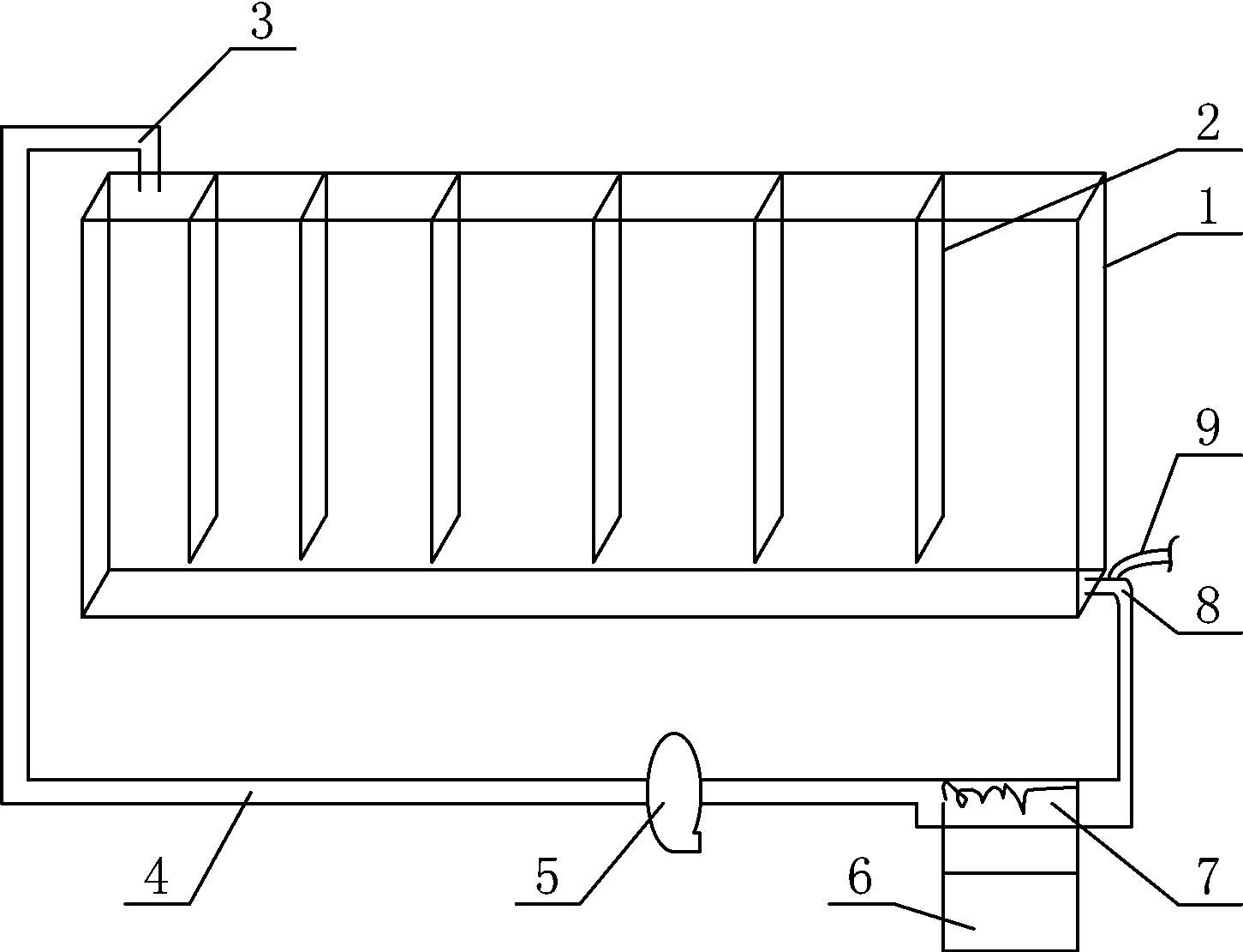
[0020] Such as figure 1 , the embodiment of the present invention comprises the cuboid shape cylinder body 1 that is made of transparent material and is closed on six sides, and the length of cylinder body 1 is much larger than its height and width, and the height of cylinder body 1 of this embodiment is 70-100cm, and length is 500-3000cm, Thickness 1-20cm.

[0021] In the cylinder body 1, a certain distance (60-100 cm in this embodiment) is fixed at every interval along the length direction (60-100 cm in this embodiment), and a vertical partition 2 that increases turbulence and strengthens the cylinder body is fixed. The distance between the end surfaces is 0-30cm (in this embodiment, the upper end of the vertical partition 2 is flush with the upper end surface of the reactor cylinder), and there is a gap of 2-10cm between the lower end of the partiti...


PUM

PropertyMeasurementUnit
heightaaaaaaaaaa
lengthaaaaaaaaaa
thicknessaaaaaaaaaa

Abstract

The invention discloses an intra-system temperature-controlled algae liquid external circulating microalgae photobioreactor, comprising a six-side closed cuboid vat body made of a transparent material, wherein two ends of the vat body in the length direction are respectively connected with a water inlet pipe and a water outlet pipe, an external circulating pipe is connected between the water inlet pipe and the water outlet pipe, and a circulating water pump is arranged on the external circulating pipe; the photobioreactor further comprises an air feeding pipe which is externally connected with a carbon dioxide pressure gas source, and the inner end opening of the air feeding pipe is close to the water outlet pipe; a heat exchanger for cooling algae liquid in the external circulating pipe is also arranged on the external circulating pipe. The algae liquid is efficiently and quickly cooled through a temperature control device of the photobioreactor, so that the purposes of saving energy and reducing consumption are achieved; closed culture of a flat photobioreactor is realized, air pollution and waste of carbon dioxide are avoided under the premise that algae cells can be fully circulated and suspended, the energy consumption of a system is reduced, and the efficiency and quality of algae cell culture are improved.

Description

[0001] technical field [0002] The invention relates to a microalgae photobioreactor. Background technique [0003] In the high temperature environment in summer, the temperature control of the algae liquid for large-scale cultivation of microalgae is very critical, because if the temperature is too high, other organisms will be seriously infected, resulting in a decrease in the production of microalgae, or even death. [0004] The existing microalgae photobioreactor system itself does not have a temperature control device, and mainly relies on controlling the overall temperature in the workshop to reduce the temperature of the algae liquid in the reactor. Commonly used cooling methods include air conditioning, rain curtains, water sprays, and sunshade nets. The main disadvantages of these methods are that the temperature adjustment speed is slow, the energy consumption is large, and the noise is very loud after the cooling and exhaust facilities are installed in the works...

Claims


Application Information

Patent Timeline
Patent Type & Authority Applications(China)
IPC IPC(8): C12M1/00C12M1/04C12M1/02
CPCC12M21/02C12M23/02C12M27/20C12M29/06C12M29/18C12M41/18
Inventor 陈勇邹宁孙东红
Owner 陈勇
Why Eureka
Try Eureka