
A temperature detection method for bus joints of gas insulated switchgear

A technology for gas-insulated switches and busbar joints, which is applied in the direction of thermometers, thermometers, thermometer parts, etc. with physical/chemical changes. It is difficult to capture fault characteristics and other problems to achieve the effect of easy detection automation, high safety and feasibility, and automatic detection

Active Publication Date: 2017-03-15
FOSHAN POWER SUPPLY BUREAU GUANGDONG POWER GRID +1
View PDF2 Cites 0 Cited by
  • Summary
  • Abstract
  • Description
  • Claims
  • Application Information

AI Technical Summary

Problems solved by technology

The method of measuring loop resistance cannot be used for live detection, and this method of measuring the resistance between the main circuit such as the bushing and the grounding switch, if the decomposition measurement is not carried out, there will be great uncertainty, that is, the number of faulty joints cannot be determined and the The problem with the location of the faulty connector
Partial discharge detection methods are difficult to formulate effective fault criteria, and the relationship between overheating and partial discharge needs to be further studied. As far as the field operation is concerned, there is a phenomenon that the partial discharge signal cannot be detected when the bus joint is overheated
The method of regularly using a hand-held infrared thermal imaging camera for inspections may not be able to detect changes in the temperature rise of the contacts due to the presence of SF6 gas between the busbar contacts and the housing, so the temperature measurement accuracy and sensitivity are low. The temperature measurement results of this method It is easy to be affected by environmental factors and detection distance, so it is difficult to capture fault characteristics, and this method is difficult to realize the integrated integration of online monitoring system. Even if there is a defect of contact deterioration, it requires operators to have rich experience to make correct judgments

Method used


Image

  • A temperature detection method for bus joints of gas insulated switchgear
  • A temperature detection method for bus joints of gas insulated switchgear
  • A temperature detection method for bus joints of gas insulated switchgear

Examples


Embodiment

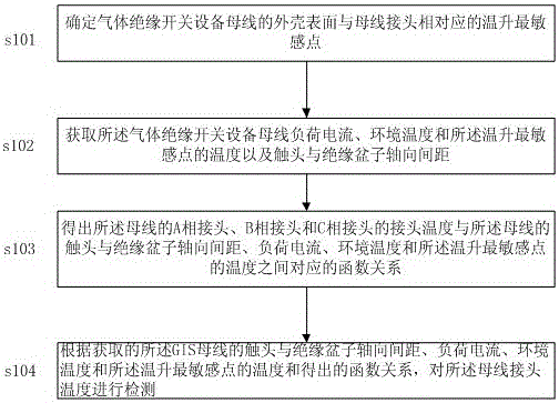
[0023] see figure 1 , is a schematic flow chart of the method for detecting the temperature of the gas-insulated switchgear bus joint of the present invention. The temperature detection method of the gas insulated switchgear bus joint of the present invention comprises the following steps:

[0024] S101 Determine the most sensitive point of temperature rise corresponding to the surface of the busbar of the gas insulated switchgear busbar and the busbar joint;

[0025] As one of the embodiments, the finite element numerical calculation method is used to determine the most sensitive point of temperature rise corresponding to the shell surface of the gas insulated switchgear busbar and the busbar joint.

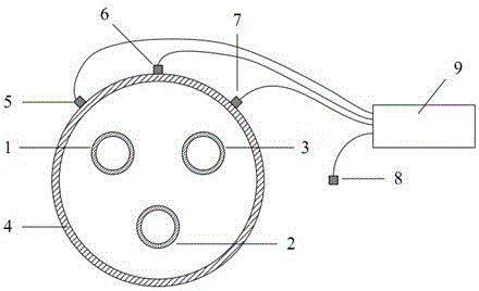
[0026] Since the hottest points reflected on the surface of the shell by joints at different positions are different, the temperature field distribution of the busbar is calculated by the finite element numerical calculation method, and the most sensitive point of the GIS secti...


PUM


Abstract

The invention provides a temperature detection method for a busbar joint of gas insulation switch equipment. The temperature detection method comprises the steps of determining the distance between a contact and an insulation spacer and the temperature rise most-sensitive point, corresponding to the busbar joint, of the shell surface of a busbar of the gas insulation switch equipment; acquiring the load current, the environment temperature and the temperature of the temperature rise most-sensitive point of the equipment busbar and the distance between the contact and the insulation spacer; obtaining the functional relationship between the joint temperature of the equipment busbar, the load current, the environment temperature and the temperature of the temperature rise most-sensitive point of the equipment busbar and the distance between the contact and the insulation spacer; detecting the temperature of the three-phase busbar joint of the equipment. By means of the temperature detection method, on-line detection of the temperature of the busbar joint of the gas insulation switch equipment can be achieved, power failure detection of a GIS is not needed, the detection result is not influenced by external environment factors, modification of the equipment structure is not needed, the safety and the feasibility are high, busbar joints of different voltage classes in a transformer substation can be detected at the same time, and detection automation can be conveniently achieved.

Description

technical field [0001] The invention relates to the technical field of temperature detection of electrical equipment busbar joints, in particular to a DC and low-frequency magnetic field signal detection device. Background technique [0002] Compared with traditional open substations, gas insulated switchgear has the advantages of less land occupation, high reliability, no pollution, convenient maintenance, and long service life. Competitive equipment has been widely used in power transmission and distribution systems at home and abroad. However, faults such as overheating or even burning of the busbar due to excessive contact resistance of the joints of the gas insulated switchgear have seriously affected the reliability and stability of the grid power supply. [0003] Aiming at the problem of failure caused by overheating of gas-insulated switchgear busbar joints, the general measurement methods currently mainly used include regular loop resistance detection, partial disc...

Claims


Application Information

Patent Timeline
Patent Type & Authority Patents(China)
IPC IPC(8): G01K11/00G01K1/20
Inventor 金向朝谢志杨关向雨黄松波舒乃秋梁家盛温可明
Owner FOSHAN POWER SUPPLY BUREAU GUANGDONG POWER GRID
Learn More