Measuring device for pipe/mold friction coefficient for pipe bending

A friction coefficient and measuring device technology, applied in the fields of friction measuring devices and friction coefficient measuring devices, can solve the problems of inability to accurately measure the friction coefficient between pipes and molds, large errors in the measurement results of the friction coefficient, and inability to process flat samples. , to achieve accurate and stable test results, easy operation, and avoid measurement errors.

Active Publication Date: 2017-09-12
NORTHWESTERN POLYTECHNICAL UNIV
View PDF6 Cites 2 Cited by
  • Summary
  • Abstract
  • Description
  • Claims
  • Application Information

AI Technical Summary

Problems solved by technology

However, when the pipe is processed into a flat sample, problems such as work hardening and surface state changes (such as reduced surface flatness and surface scratches) will occur, resulting in large errors in the measurement results of the friction coefficient. For some high-strength pipes ( Such as TC4 titanium alloy pipes, etc.) will also have problems such as the inability to process flat samples; in addition, the existing sheet friction test technology cannot more realistically simulate the contact conditions under the interactive influence of process parameters such as temperature, pressure, and bending speed during the bending process of the pipe For example, the friction behavior of the torsional compression test is the circular repeated friction between the pipe and the mold, while the real friction behavior of the pipe bending process is the one-way friction between the inner and outer walls of the pipe and different molds, which will lead to distortion of the simulation test results
Therefore, the existing friction testing device cannot accurately measure the friction coefficient between the pipe / mold during the pipe bending process

Method used


Image

  • Measuring device for pipe/mold friction coefficient for pipe bending
  • Measuring device for pipe/mold friction coefficient for pipe bending
  • Measuring device for pipe/mold friction coefficient for pipe bending

Examples


Embodiment Construction

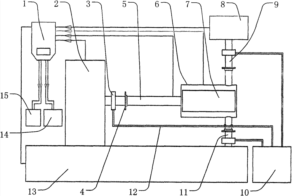
[0038] This embodiment is a measuring device for the friction coefficient of the pipe / mold in the pipe bending forming process, such as figure 1 As shown, the structure of this embodiment includes: charge amplifier 1, horizontal transmission sensor platform 2, horizontal transmission rod 5, resistance heating furnace 6, friction pair device 7, hydraulic transmission sensor platform 8, upper mold fixing rod 9, water cooling pump 10 , water-cooled pipe 12, water-cooled box 3, heat sink 4, support base 11, machine base 13, A / D acquisition computer 14 and temperature controller 15. The horizontal transmission sensor platform 2 is fixed on the machine base 13, the horizontal transmission rod 5 is connected with the horizontal transmission sensor platform 2, the right end part of the horizontal transmission rod 5 is connected with the guide rail of the support seat 13, and is located above it, and the friction pair device 7 is located On the right end of the horizontal transmission ...


PUM


Abstract

The invention relates to a device for measuring a pipe / die friction coefficient during pipe bending forming. The device includes: a horizontal transmission sensor platform, a hydraulic sensor platform, a cooling system, a friction pair instrument, a resistance heating furnace, a temperature sensor, a friction sensor, a charge amplifier, a temperature control instrument and an A / D acquisition computer. A horizontal transmission rod matches with a pipe die fixed station, a pipe sample is fixed on a sample fixation table, an upper die is fixed at the lower end of an upper die fixation rod, which is assembled with the hydraulic sensor platform, the cooling system is assembled with the horizontal transmission rod, the upper die fixation rod and a support seat, and the hydraulic sensor platform, the horizontal transmission sensor platform and all the sensors are respectively connected to the A / D acquisition computer through the charge amplifier. The device provided by the invention can accurately measure the friction coefficient between the pipe inner wall, outer wall and the die under different temperatures, pressures, lubrication states and other conditions, has the advantages of high degree of automation, simple operation and high measurement accuracy, and has a wide range of application for measurement of the pipe forming friction coefficient.

Description

technical field [0001] The invention relates to a friction measurement device in the technical field of material processing, in particular to a friction coefficient measurement device for pipes / moulds in different lubrication states during the numerical control bending forming process of pipes. Background technique [0002] Bending pipe parts are widely used in high-tech fields such as aerospace, automobile, energy and chemical industry because they can easily meet the urgent requirements of lightweight and toughening products in the field of advanced plastic forming. The CNC pipe bending technology is not only easy to realize the precise forming of the plastic bending of the pipe, but also has the characteristics of high efficiency, energy saving and stable quality, which is convenient for digitalization and high technology. Therefore, the numerical control bending of the pipe has developed into an advanced and applicable technology. However, pipe NC bending is a complex ph...

Claims


Application Information

Patent Timeline
Patent Type & Authority Patents(China)
IPC IPC(8): G01N19/02
Inventor 李恒马俊杨合王丹
Owner NORTHWESTERN POLYTECHNICAL UNIV
Why Eureka
Try Eureka