Tray and plasma processing equipment

A plasma and tray technology, applied in semiconductor/solid-state device manufacturing, discharge tubes, electrical components, etc., can solve the problem of reducing the process uniformity of plasma processing equipment, the poor temperature uniformity of the processed workpiece 2, and the temperature difference between the temperature and the middle area And other problems, to improve the effect of heat exchange, improve process uniformity, improve the effect of temperature uniformity

Active Publication Date: 2014-11-05
BEIJING NAURA MICROELECTRONICS EQUIP CO LTD
View PDF8 Cites 6 Cited by
  • Summary
  • Abstract
  • Description
  • Claims
  • Application Information

AI Technical Summary

Problems solved by technology

[0004] The above-mentioned plasma processing equipment inevitably has the following problems in practical applications, that is, since the middle air inlet 32 ​​is located at a circumference whose radius is about half of the radius of the loading position, the heat exchange gas passes through the middle air inlet. 32 The diffusion radius diffused to the surroundings often cannot reach the edge area of ​​the workpiece 2 (the area of ​​3-5 mm on the edge of the loading position), resulting in poor heat exchange effect between the heat exchange gas and the edge area of ​​the workpiece 2 , which will cause the temperature difference between the edge region of the processed workpiece 2 and the temperature of the middle region, so that the temperature uniformity of the processed workpiece 2 is poor, thereby reducing the process uniformity of the plasma processing equipment

Method used


Image

  • Tray and plasma processing equipment
  • Tray and plasma processing equipment
  • Tray and plasma processing equipment

Examples


Embodiment Construction

[0040] In order for those skilled in the art to better understand the technical solution of the present invention, the tray and the plasma processing equipment provided by the present invention will be described in detail below with reference to the accompanying drawings.

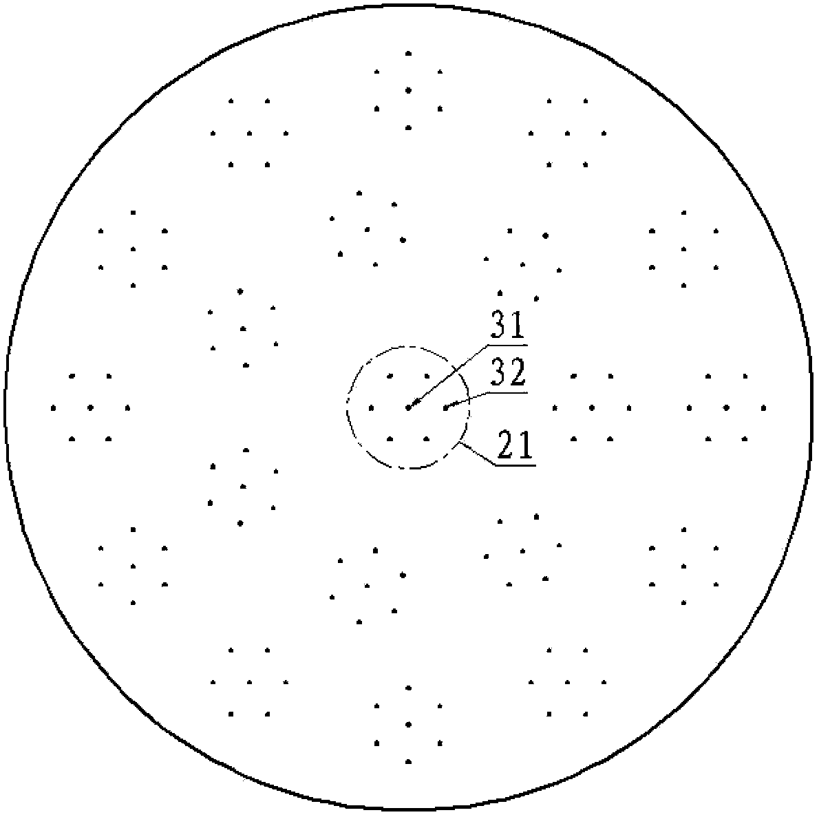
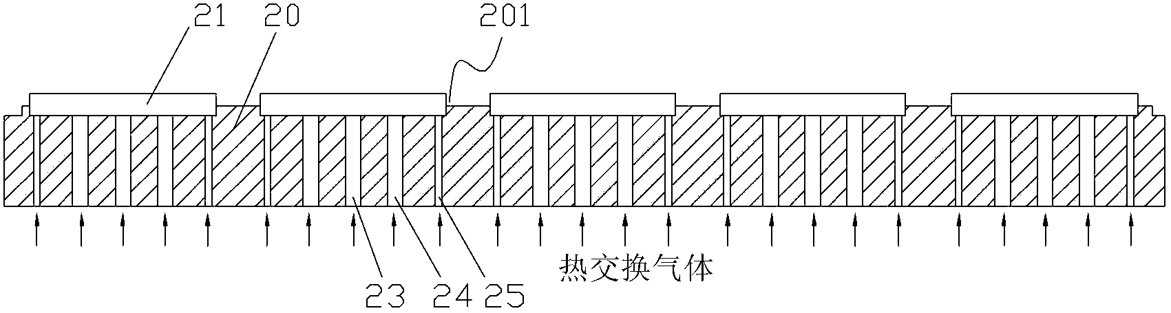
[0041] image 3 A cross-sectional view of the tray provided for the present invention. Figure 4 for image 3 A partial top view of a loading position of the middle tray. Please also refer to image 3 and Figure 4 , the tray 20 is used to carry the workpiece 21 to be processed, and adjust the temperature of the workpiece 21 to be processed by means of heat exchange gas. , and, in this embodiment, a groove is formed on each loading position 201, and the workpiece 21 to be processed is placed in the groove. The position of the workpiece 21 to be processed on the pallet 20 can be limited by means of the groove, so that the workpiece 21 to be processed can be prevented from shifting relative to the pallet...


PUM


Abstract

Disclosed are a substrate bearing device (20) and plasma processing equipment. An upper surface of the substrate bearing device (20) is provided with a plurality of substrate mounting locations (201), and heat-exchange gas inlet passages (23, 24, 25) are arranged in the substrate bearing device (20) corresponding to each substrate mounting location (201), so as to guide a heat exchange gas to the upper surface of the substrate mounting location (201). The heat-exchange gas inlet passages comprise peripheral inlet passages and a middle inlet passage, wherein gas inlets (23, 24, 25) of the peripheral inlet passages and the middle inlet passage are all in communication with an external gas source; gas outlets of the peripheral inlet passages are arranged in the peripheral region of the upper surface of the substrate mounting location (201); and a gas outlet of the middle inlet passage is arranged in the middle region of the upper surface of the substrate mounting location (201). The substrate bearing device (20) and the plasma processing equipment can improve the heat exchange effect of the peripheral region of a processed workpiece (21), so that the temperature of the peripheral region and the middle region of the processed workpiece (21) can be enabled to tend to be uniform, and then the uniformity of the plasma processing technology can be improved.

Description

technical field [0001] The invention relates to the technical field of microelectronic processing, in particular to a tray and plasma processing equipment. Background technique [0002] Plasma processing equipment is a common equipment for processing semiconductor devices. During the process of etching, sputtering and chemical vapor deposition, etc., in order to improve the production efficiency of plasma processing equipment and reduce production costs, generally larger size The tray is used to carry multiple workpieces to be processed and transport them to the reaction chamber at the same time, so as to realize simultaneous processing of multiple workpieces to be processed. [0003] figure 1 It is a structural schematic diagram of the existing plasma processing equipment. Such as figure 1 As shown, the plasma processing equipment includes a reaction chamber 1 and a tray 3 . Wherein, a base 5 is arranged in the reaction chamber 1, and an electrostatic chuck 4 is fixed o...

Claims


Application Information

Patent Timeline
Patent Type & Authority Applications(China)
IPC IPC(8): H01L21/687H01J37/32H01J37/02
CPCH01L21/67109H01L21/68771
Inventor 张宝辉李东三刘利坚栾大为高福宝杨智慧李宗兴
Owner BEIJING NAURA MICROELECTRONICS EQUIP CO LTD
Why Eureka
Try Eureka