
Millimeter-wave multi-channel space waveguide power distribution synthesizer and method

A technology of millimeter wave and space wave, which is applied in the direction of waveguide devices, circuits, electrical components, etc., can solve the problem of space power distribution/combiner stability and reliability reduction, poor isolation of amplifier unit branches, and increased processing of three-dimensional structures Difficulty and other issues, to achieve the effect of improving synthesis efficiency, low power loss, and large output power

Active Publication Date: 2014-11-05
CHINA ELECTRONIS TECH INSTR CO LTD
View PDF4 Cites 11 Cited by
  • Summary
  • Abstract
  • Description
  • Claims
  • Application Information

AI Technical Summary

Problems solved by technology

However, the above-mentioned waveguide-based spatial power distribution / combiner has the following disadvantages: (1) The three-dimensional structure adopted by the waveguide-based spatial power distribution / combiner increases the processing difficulty, and the assembly is complicated and the production cost is high; (2) Since the coaxial transmission line is used as the transmission medium of the multi-channel power distribution and synthesis section, as the operating frequency increases, the loss of the coaxial transmission line becomes larger, and the synthesis efficiency decreases rapidly; (3) this power distribution / combiner is due to It is impossible to add isolation resistors, and the isolation between the branches of each amplifying unit is poor, which reduces the stability and reliability of the waveguide-based spatial power distribution / combiner

Method used


Image

  • Millimeter-wave multi-channel space waveguide power distribution synthesizer and method
  • Millimeter-wave multi-channel space waveguide power distribution synthesizer and method
  • Millimeter-wave multi-channel space waveguide power distribution synthesizer and method

Examples


Embodiment Construction

[0044] Below in conjunction with accompanying drawing and specific embodiment the present invention is described in further detail:

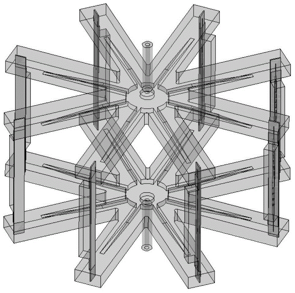
[0045] combine figure 2 and image 3 As shown, the millimeter-wave multi-channel spatial waveguide power divider includes a 4-way waveguide power divider and four 2-way waveguide power dividers.

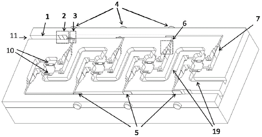
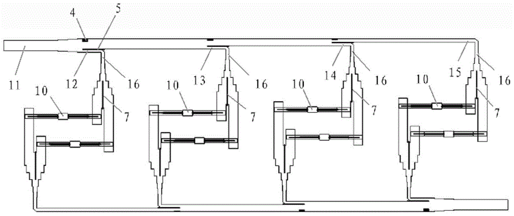
[0046] Such as Figure 4 As shown, the 4-way waveguide power divider includes a first rectangular waveguide 1, a first stepped tapered waveguide 2 and an extended waveguide 3, wherein the first rectangular waveguide 1 is connected to the narrow end side of the first stepped tapered waveguide 2, and the extended waveguide The waveguide 3 is connected on the wide end side of the first step-taper waveguide 2 .

[0047] One first port 11 is provided on the first rectangular waveguide 1 , and four second ports 12 , 13 , 14 , 15 are provided on the extended waveguide 3 . There are three sets of first power adjustment components inside the extended waveg...


PUM


Abstract

The invention discloses a millimeter-wave multi-channel space waveguide power distribution synthesizer and a method. The power distributor comprises a four-channel waveguide power distributors and four two-channel waveguide power distributors, a first port, four second ports and a first power allocation part are arranged in the four-channel waveguide power distributor, the first power allocation part is used for dividing one path of signal of electromagnetic wave into four paths of signals in equal proportion, a third port, two fourth ports and a second power allocation part are arranged in the each two-channel waveguide power distributor, the third port is connected with each second port, the second power allocation part is used for further dividing the four paths of signals into eight paths of signals in equal proportion, each path of signal is separately subjected to power amplification, the single path of signal subjected to amplification pass through the power synthesizer having the same structure with the power distributor, and multi-path power synthesis of electromagnetic signals are completed. The millimeter-wave multi-channel space waveguide power distribution synthesizer has the advantages of wide band, high capacity, high isolation, high efficiency, low loss and the like.

Description

technical field [0001] The present invention relates to a millimeter-wave multi-channel spatial waveguide power distribution / combiner suitable for millimeter-wave frequency bands, a power distribution method using the millimeter-wave multi-channel spatial waveguide power distribution / combiner, and a power distribution method using the millimeter-wave multi-channel spatial waveguide power Power Combining Method for Distributor / Combiner. Background technique [0002] With the development of millimeter-wave high-power test technology, the output power of a single solid-state power amplifier chip can no longer meet the requirements of the test system for output power. The output power of the system. Common power dividers / combiners include planar circuit power dividers / combiners and radial waveguide-based spatial power dividers / combiners. The planar circuit power distribution / combiner mostly adopts the cascaded structure of multi-stage Wilkinson power dividers. As the number of...

Claims


Application Information

Patent Timeline
IPC IPC(8): H01P5/12
Inventor 王涛张永虎宁曰民姜万顺刘金现朱伟峰
Owner CHINA ELECTRONIS TECH INSTR CO LTD
Learn More