
Bus conductor assembly tool

A technology for assembling tooling and conductors, applied in cable laying equipment and other directions, can solve the problems of reducing the size of the tooling, easy to deviate, and inconvenient to take out the tooling, and achieve the effect of shortening installation time, reducing labor intensity and simple structure

Inactive Publication Date: 2014-11-05
STATE GRID CORP OF CHINA +1
View PDF9 Cites 7 Cited by
  • Summary
  • Abstract
  • Description
  • Claims
  • Application Information

AI Technical Summary

Problems solved by technology

[0003] 1. When used in a small-diameter busbar barrel (with an inner diameter of 500mm or less), it was found that the tooling was too long in its longitudinal dimension; due to the too long longitudinal dimension, it was inconvenient for the tooling to be taken out of the busbar barrel or casing when the insulating basin was used to encapsulate the busbar
[0004] 2. The size of the tooling is reduced in proportion. When it is used in a small-diameter busbar barrel, its own structural strength cannot meet the problem of supporting the weight of the conductive rod
[0005] 3. The tooling center of this series, the hollow tube used to support the conductive rod, its diameter size is not adjustable, it can only be adjusted with filler
[0006] 4. The front-line workers reported that this series of tooling is no problem for mass assembly of busbars and bushings in the factory, but its overall structure is heavy and not suitable for long-distance travel by workers.
[0008] However, of these two methods, the first method cannot be used for positioning and centering installation; the second method has the problem of easy deviation when the tooling is rolling. If the length of the busbar barrel is short, the problem of tooling deviation will not be affected much. , if the busbar barrel is too long and the tooling deviates, it can directly cause the conductive rod to slide laterally from the tooling, and the busbar barrel will be damaged if it is light, and the hands will be injured if it is serious

Method used


Image

  • Bus conductor assembly tool

Examples


Embodiment Construction

[0020] The present invention will be further described in detail below in conjunction with the accompanying drawings and specific embodiments.

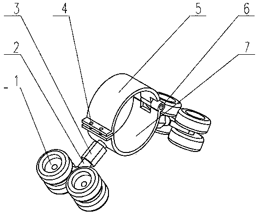
[0021] See attached figure 1 , this embodiment includes a supporting plate 7 and a pinch plate 5, one end of the pinching plate 5 and the supporting plate 7 is hinged by a pin 6, and the other end is fixedly connected, and the supporting plate 7 and the pinching plate 5 are closed to form a closure that can accommodate the conductive rod. hole (i.e. clamping hole); the two sides of the supporting plate 7 are respectively provided with an adjusting screw, the supporting plate 7 is connected with the set wheel supporting frame through the adjusting screw 3, and the other end of the wheel supporting frame 2 is provided with two A wheel 1 that can move in the bus barrel, the wheel 1 is arranged along the axial direction of the bus barrel, and the height of the supporting plate 7 is adjusted by the adjustment screw 3. When not in use, ro...


PUM

PropertyMeasurementUnit
Angleaaaaaaaaaa

Abstract

The invention discloses a bus conductor assembly tool. The bus conductor assembly tool is characterized by comprising a supporting plate and a buckling plate hinged to one end of the supporting plate and fixedly connected with the other end of the supporting plate. The supporting plate and the buckling plate form a clamping hole for a conducting rod to pass through after being closed. The two sides of the supporting plate are respectively connected with a wheel supporting frame through an adjusting screw, the other end of each wheel supporting frame is provided with two or more wheels capable of moving in bus cylinders, the wheels are arranged in the axial direction of the bus cylinders, and the height of the supporting plate can be adjusted through the adjusting screws. The bus conductor assembly tool is simple in structure and convenient to use and is a two-point-centering type device. The height of the supporting plate can be adjusted. Construction can be carried out after the supporting plate and the buckling plate clamp the conducting rod. The bus conductor assembly tool can lower the labor intensity, shorten the installation time and prevent the bus cylinders, a sleeve and the conducting rod from being bumped or scratched, is light in overall weight, can be disassembled into parts and components to be carried and can be conveniently used for maintaining the bus cylinders or the sleeve on the site in the outdoors.

Description

technical field [0001] The invention relates to a bus conductor assembly tool. Background technique [0002] At present, in the installation and maintenance work of electric equipment, there are many places that need to use level gauges. However, some of them are found when using the series of tooling disclosed in the invention patent application No. The similar three-point centering tool has good positioning, centering, and installation of preventing the conductive rod from "lowering" (that is, tilting) when installing the conductive rod in the large-diameter busbar barrel and casing (800 mm to 1000 mm inner diameter) Advantage. But with this type of four-link support system, the following problems are found in the production process: [0003] 1. When used in a small-diameter busbar barrel (with an inner diameter of 500mm or less), it was found that the tooling was too long in its longitudinal dimension; due to the too long longitudinal dimension, it was inconvenient for ...

Claims


Application Information

Patent Timeline
IPC IPC(8): H02G1/08
Inventor 郭小燕闫佳文杨军强
Owner STATE GRID CORP OF CHINA
Learn More