
A Pulse Width Limiting Circuit for Inverter Power Supply

A technology of limiting circuit and inverter power supply. It is applied in the direction of conversion equipment with intermediate conversion to AC, which can solve the problems of large heat in the machine, high product cost, and low machine efficiency.

Active Publication Date: 2016-08-17
浙江钧迪电子科技有限公司
View PDF5 Cites 0 Cited by
  • Summary
  • Abstract
  • Description
  • Claims
  • Application Information

AI Technical Summary

Problems solved by technology

[0004] The present invention provides a new pulse width limiting circuit for inverter power supply aiming at the defects of large internal heat, high product cost and low machine efficiency in the prior art.

Method used


Image

  • A Pulse Width Limiting Circuit for Inverter Power Supply

Examples


Embodiment 1

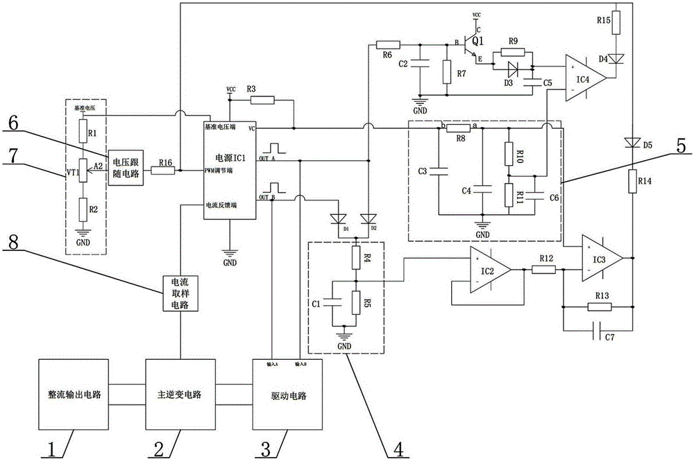
[0022] Such as figure 1As shown, a pulse width limiting circuit of an inverter power supply includes a main inverter circuit 2, a rectification output circuit 1, a drive circuit 3, a current sampling circuit 8, and a power supply IC1. The rectification output circuit 1 and the drive circuit 3 are respectively connected to the main inverter circuit 2, the main inverter circuit 2 is connected to the current feedback terminal of the power supply IC1 through the current sampling circuit 8, and the output terminal OUTA and the output terminal OUTB of the power supply IC1 are respectively connected to the drive circuit 3, It is characterized in that it also includes a first voltage divider circuit 7, a voltage follower circuit 6, an integration circuit 4, a second voltage divider circuit 5, an operational amplifier IC2, and an operational amplifier IC3. Circuit 6. The current-limiting resistor R16 is connected to the PWM adjustment terminal of the power supply IC1, and the other is ...


PUM


Abstract

The invention discloses a pulse width limiting circuit of an inverter power supply, which includes a main inverter circuit, a rectification output circuit, a drive circuit, a current sampling circuit, and a power supply IC1, and also includes a first voltage dividing circuit, a voltage follower circuit, an integrating circuit, The second voltage divider circuit, the operational amplifier IC2, and the operational amplifier IC3. The pulse width limiting circuit of the inverter power supply can effectively adjust the output pulse width, so that the circuit always works in the safe current range, effectively avoiding the occurrence of magnetic bias phenomenon, and the circuit structure is simple, without reducing the switching speed of the power tube and increasing The absorbed energy of the power tube absorption circuit greatly reduces the turn-on and turn-off losses of the power tube and reduces the production cost.

Description

technical field [0001] The invention relates to an inverter power supply, in particular to a pulse width limiting circuit of the inverter power supply. Background technique [0002] Inverter welding power supply is referred to as inverter power supply, which has the advantages of high efficiency and light weight. At present, the annual domestic output has reached 10 million units, and it has begun to be used by more and more families and units. The inverter power supply industry has a broad prospect, leading more and more enterprises to set foot in this field. Under the new development form, the functions of the inverter power supply are getting stronger and the price is getting lower and lower, resulting in various costs for enterprises. Continuously improving, profits become more and more meager. Therefore, how to reduce product after-sales cost, how to improve product reliability, and how to reduce product production cost without reducing product reliability have become ...

Claims


Application Information

Patent Timeline
Patent Type & Authority Patents(China)
IPC IPC(8): H02M3/28
Inventor 殷杰熊怡军舒展鹏
Owner 浙江钧迪电子科技有限公司
Learn More