
Chip flattening method

A planarization method and chip technology, which is applied in the direction of grinding devices, electrical components, grinding machine tools, etc., can solve the problems of difficulty in controlling the planarization of the chip surface, dish-shaped depressions of silicon wafers, and the reduction of global planarization of the surface of silicon wafers, etc. , to achieve the effect of improving global planarization, improving yield rate, and improving chip surface planarization

Inactive Publication Date: 2014-11-12
ACM RES SHANGHAI
View PDF6 Cites 2 Cited by
  • Summary
  • Abstract
  • Description
  • Claims
  • Application Information

AI Technical Summary

Problems solved by technology

However, during the entire grinding process, if the silicon wafer is ground with a large down force, it is easy to produce dish-shaped depressions on the silicon wafer, which reduces the global planarization of the silicon wafer surface, and more importantly, it is difficult to planarize the chip surface on the silicon wafer. good control

Method used


Image

  • Chip flattening method
  • Chip flattening method
  • Chip flattening method

Examples


Embodiment Construction

[0020] In order to describe the technical content, achieved goals and effects of the present invention in detail, the following will be described in detail in conjunction with the embodiments and accompanying drawings.

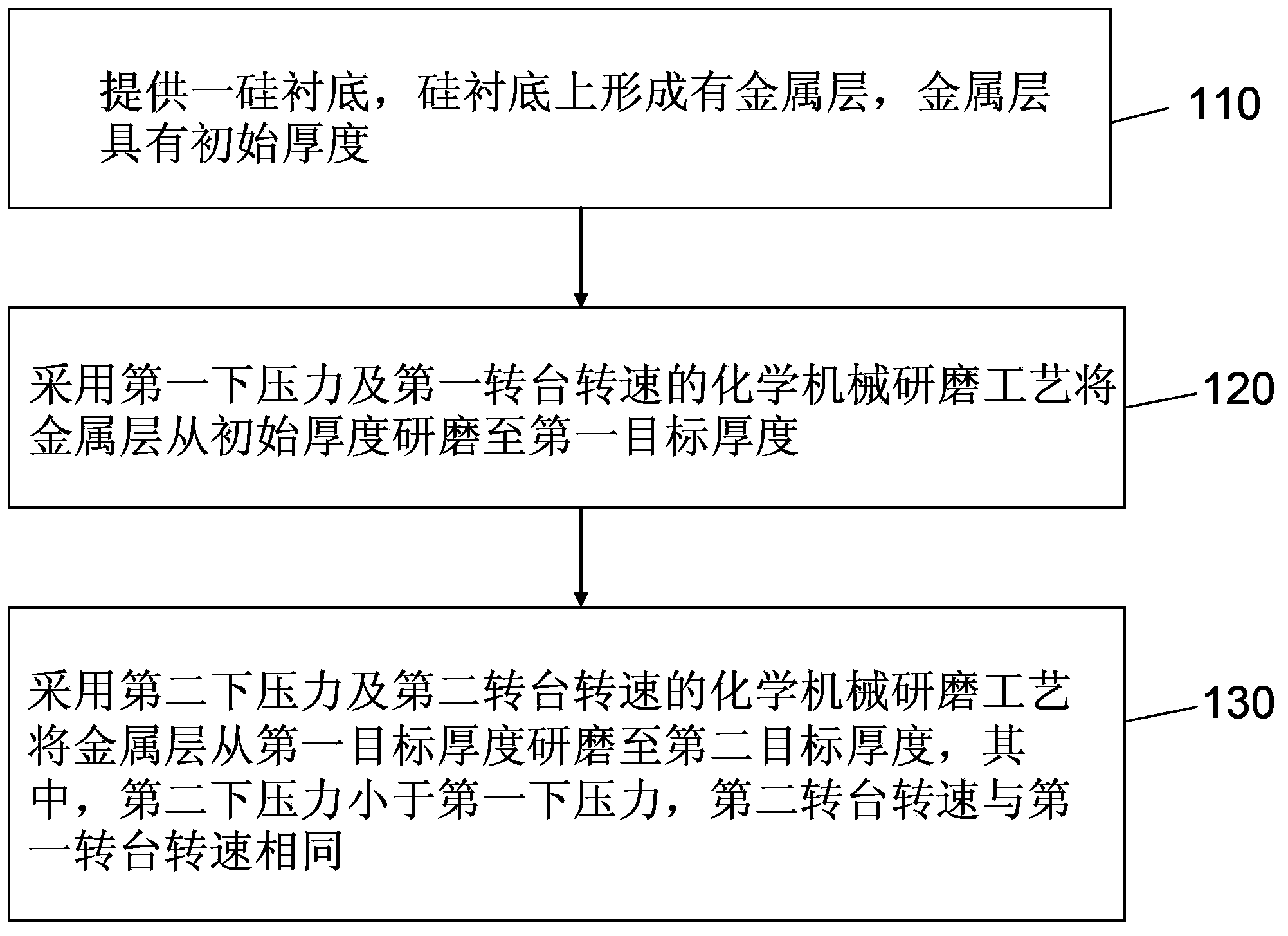
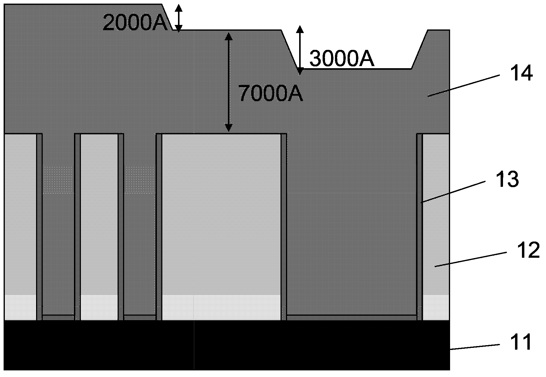
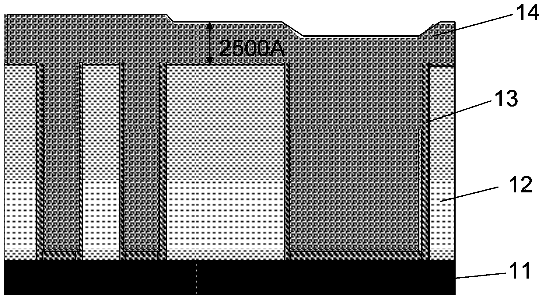
[0021] see figure 1 and Figures 2A-2C , discloses an embodiment of the chip planarization method according to the present invention. In this embodiment, the chip planarization method includes the following steps:

[0022] S110: providing a silicon substrate 11, a metal layer 14 is formed on the silicon substrate 11, the metal layer 14 has an initial thickness, and the initial thickness is 6000-10000 angstroms;

[0023] S120: Grinding the metal layer 14 from an initial thickness to a first target thickness by using a chemical mechanical polishing process with a first down force and a first rotational speed of the turntable. Wherein, the first downforce is set at 1.8-2.3 psi, the first turntable speed is set at 70-150 rpm, and the first target thickness is 1...


PUM


Abstract

The invention discloses a chip flattening method. The chip flattening method includes: providing a silicon substrate and forming a metal layer with an initial thickness on the silicon substrate; grinding the metal layer by a chemical mechanical grinding technology with first pressing force and a first rotary table rotation speed so as to enable the metal layer to be changed from the initial thickness to a first target thickness; grinding the metal layer by the chemical mechanical grinding technology with second pressing force and a second rotary table rotation speed so as to enable the metal layer to be changed from the first target thickness to a second target thickness, wherein the second pressing force is smaller than the first pressing force, and the second rotary table rotation speed is identical to the first rotary table rotation speed. The chip flattening method has the advantages that the metal layer is grinded at the high speed with the larger pressing force and then grinded at the high speed with the smaller pressing force, overall flattening of the surface of the silicon substrate can be improved, flattening of the surface of a chip can be improved, and thereby yield of a semiconductor device can be increased. According to the chip flattening method, the metal layer can be grinded at the high speed with the smaller pressing force and then grinded at the same speed with the larger pressing force.

Description

technical field [0001] The invention relates to the technical field of semiconductor device manufacturing technology, in particular to a chip planarization method. Background technique [0002] The rapid development of computer, communication and network technology has higher and higher requirements on semiconductor devices. Semiconductor devices are constantly developing in the direction of high speed, high integration, high density and high performance, resulting in the continuous shrinking of their feature size and the continuous reduction of metal interconnection. The number of interconnected wiring layers continues to increase. In the three-dimensional structure of multilayer wiring, it is required not only to planarize the surface of the entire silicon chip including all chips (global planarization), but also to planarize the surface of each chip. Because whether it is the uneven surface of the silicon wafer or the uneven surface of the chip, it will have a negative i...

Claims


Application Information

Patent Timeline
IPC IPC(8): B24B37/013B24B37/04H01L21/321
CPCB24B37/013B24B37/04H01L21/3212
Inventor 王坚杨贵璞王晖
Owner ACM RES SHANGHAI
Learn More