Electromagnetism dynamic loading device

A dynamic loading, electromagnetic technology, applied in vibration suppression adjustment, spring/shock absorber, mechanical equipment, etc., can solve the problem of inability to apply or offset dynamic axial force balance, achieve structural optimization, simple and easy manufacturing process. Effect

Inactive Publication Date: 2014-11-12
XIDIAN UNIV
View PDF6 Cites 7 Cited by
  • Summary
  • Abstract
  • Description
  • Claims
  • Application Information

AI Technical Summary

Problems solved by technology

[0009] The purpose of the present invention is to overcome the problem that the method of eliminating or balancing the axial force parallel to the axis in the prior art cannot balance, apply or counteract the dynamic axial force

Method used


Image

  • Electromagnetism dynamic loading device
  • Electromagnetism dynamic loading device
  • Electromagnetism dynamic loading device

Examples


Embodiment 1

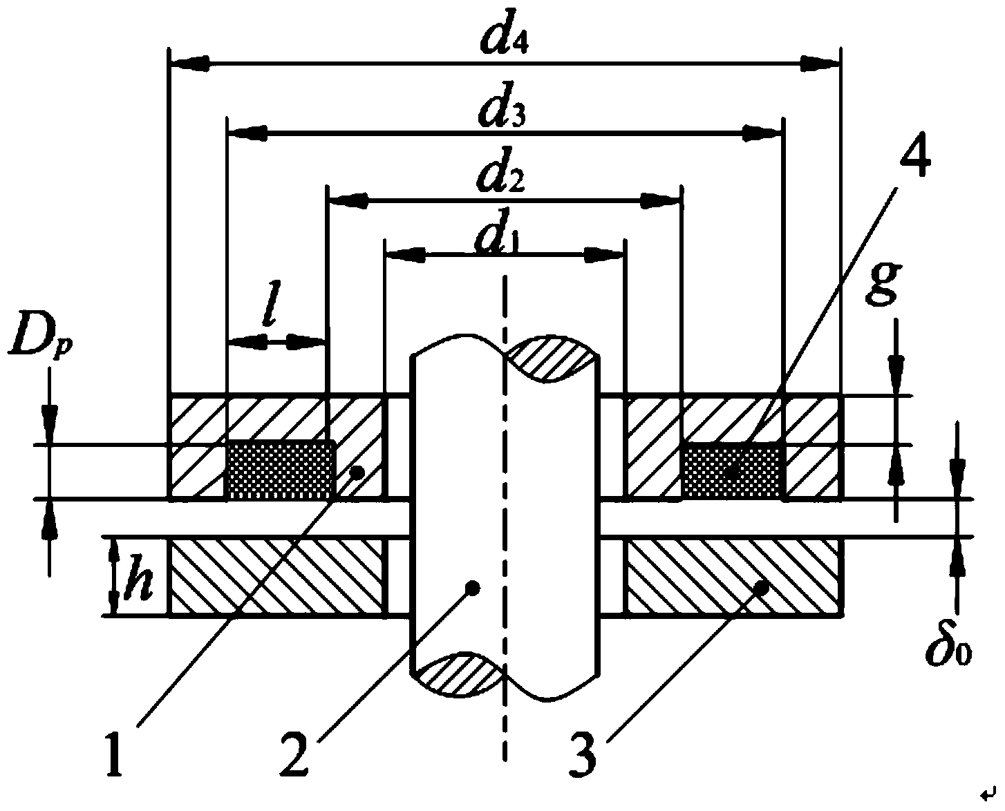
[0028] An electromagnetic dynamic loading device, comprising an annular electromagnetic end cover 1 and a flange 3 connected to the electromagnetic end cover 1, the electromagnetic end cover 1 is provided with an annular coil slot, and the annular coil slot is provided with There is a conductive coil 4 that can pass through the current; the inner side of the electromagnetic end cover 1 is also fixedly connected with an electromagnet core 2, and the electromagnetic core 2 is arranged on the inner side of the conductive coil 4; the electromagnetic core 2 is cylindrical Structure; the conductive coil 4 is placed in the annular coil slot, and is filled with insulating glue.

[0029] The above-mentioned electromagnetic dynamic loading device also includes a variable current regulator, the port of the conductive coil 4 is electrically connected to the output end of the variable current regulator; the current adjustment range of the variable current regulator is 0-10A; There is a gap...

Embodiment 2

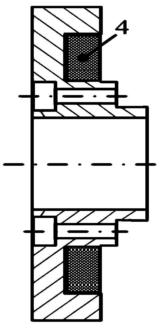
[0089] According to the calculation results of the above-mentioned embodiment 1 and the actual installation requirements, the electromagnetic end cover is designed in detail, and the material is 45 steel. The flange matched with the electromagnetic end cover 1 is made of 45 steel.

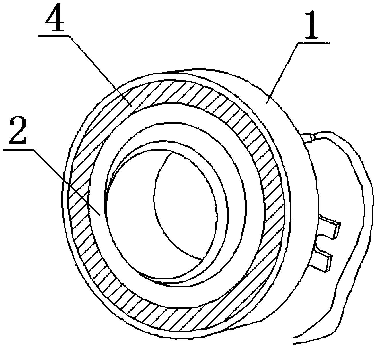
[0090] The structure diagram of electromagnetic end cover 1 is shown in figure 2 After the processing is completed, wind the electromagnetic coil in the groove, and then fix it with latex paint. The completed electromagnetic end cover 1 is as image 3 shown.

[0091] 1) Selection of adjustable current regulator

[0092] The electromagnet needs to provide a stable DC power supply, calculated from the above

[0093] I 0 =5.6A,P 0 =I 0 2 R t =27W, U 0 =P 0 / I 0 =4.8V, where R t = 0.86Ω.

[0094] Generally, the maximum current

[0095] I max =1.12I 0 =1.12×5.6=6.3A

[0096] The maximum output power is 35W and the maximum voltage is 5.6V.

[0097] According to the above calculation re...

Embodiment 3

[0111] In the above-mentioned embodiment, the current size loaded on the conductive coil 4 is manually controlled and adjusted by the variable current regulator, so as to realize the purpose of adjusting the electromagnetic field force; the difference from the above-mentioned embodiment is that the adjustment of the current can not only be adjusted by It can be adjusted manually, and it can also be connected with a variable current regulator through a controller, industrial computer or control platform to realize automatic adjustment of the current.

[0112] The axial electromagnetic force provided by the electromagnetic dynamic loading device is limited by the current variation range and temperature rise of the variable current regulator, and a cooling device can be added if necessary.

[0113] The operating environment temperature of the electromagnetic dynamic loading device system is from room temperature to 40°C, and the allowable temperature rise is less than 60°C.

[01...


PUM


Abstract

The invention belongs to the technical field of mechanical loading devices, and particularly relates to an electromagnetism dynamic loading device to solve the problem that according to a method for eliminating or balancing parallel axial force of axes in the prior art, the dynamic axial force cannot be balanced or exerted or offset. The electromagnetism dynamic loading device comprises an annular electromagnetic end cover and a flange connected with the electromagnetic end cover. An annular coil groove is formed in the electromagnetic end cover and internally provided with a wire ring, and direct current flows through the wire ring. An electromagnetic iron core is fixedly connected to the inner side of the electromagnetic end cover. The electromagnetism dynamic loading device overcomes the defects that according to the existing axial force balancing equipment and device, the dynamic axial force cannot be rapidly, effectively, easily and conveniently balanced, and the manufacturing process is simple and easy to perform; the structure of the electromagnetism dynamic loading device is optimized, and the effect of balancing or exerting or offsetting the large axial force can be achieved. The electromagnetism dynamic loading device has high engineering value in preventing dynamic axial force produced in operation of turbo machines and the like.

Description

technical field [0001] The invention belongs to the technical field of mechanical loading devices, and in particular relates to an electromagnetic dynamic loading device. Background technique [0002] When most impeller machines are running, due to the asymmetric pressure distribution of the fluid on the impeller, the rotating parts will be subjected to an axial force parallel to the axis. In order to ensure the normal operation of this type of equipment, measures must be taken to eliminate or balance the axial force. At present, there are many techniques for balancing the static axial force, while the balance of the dynamic axial force and comprehensive consideration of other constraints (including bearings and machinery) Sealing) and other issues are less studied; no relevant patented technology and equipment research. [0003] The main implementation methods and characteristics of static axial force balance are summarized as follows: [0004] 1) Thrust bearings are used...

Claims


Application Information

Patent Timeline
Patent Type & Authority Applications(China)
IPC IPC(8): F16F15/00
Inventor 张国渊赵伟刚段清娟陈永琴纪峰
Owner XIDIAN UNIV
Why Eureka
Try Eureka