Light cone system for cold light source focusing

A technology of cold light source and light cone, which is applied in the field of light cone system to achieve the effect of low cost, reliable performance and high focusing efficiency

Active Publication Date: 2014-11-12
ATTACHED OBSTETRICS & GYNECOLOGY OSPITAL MEDICALCOLLEGE ZHEJIANG UNIV +1
View PDF5 Cites 4 Cited by
  • Summary
  • Abstract
  • Description
  • Claims
  • Application Information

AI Technical Summary

Problems solved by technology

There is no focused light cone mentioned in this patent on the market for medical light sources

Method used


Image

  • Light cone system for cold light source focusing
  • Light cone system for cold light source focusing

Examples


Embodiment 1

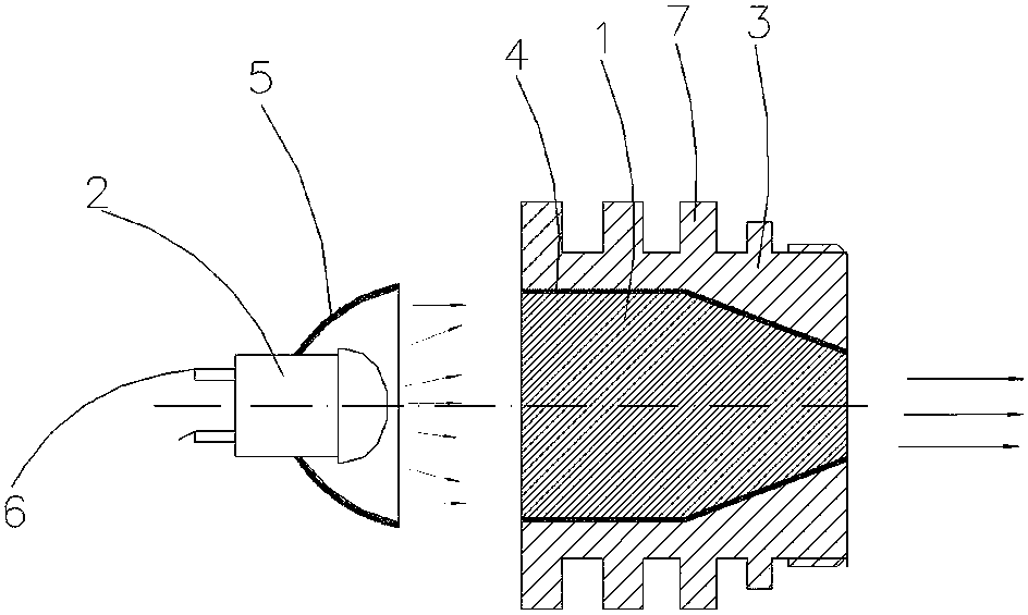
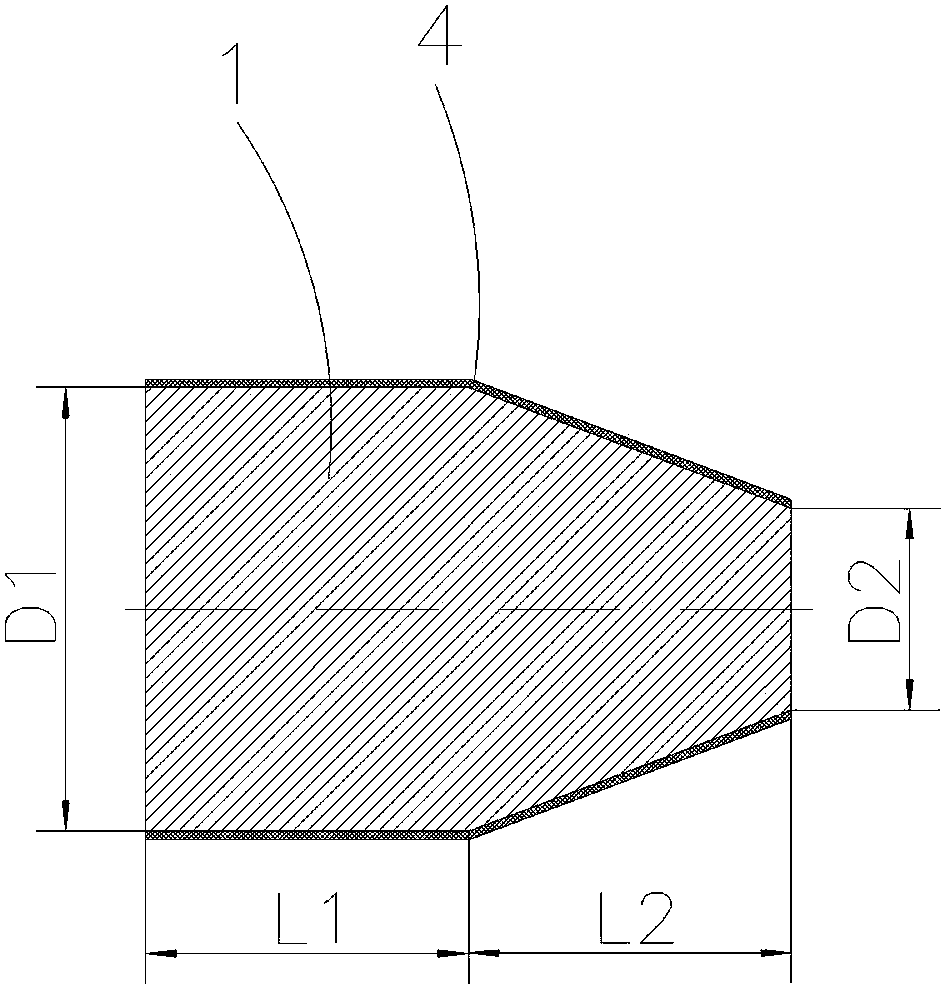
[0014] Embodiment 1: as figure 1 and figure 2 As shown, a light cone system for cold light source focusing includes a glass light cone 1 and a gas discharge lamp 2, the roughness of the outer surface of the glass light cone 1 is 0.006 microns, and the glass light dimension 1 coat There is a heat sink 3, the outer surface of the glass light beam 1 is covered with a total reflection film layer 4 in contact with the heat sink 3, in the glass light cone 1: L2=D1=3-100mm, L1= L2+(D1+D2)÷2=3-100mm; the gas discharge lamp 2 is covered with a reflective bowl 5, and the reflective bowl 5 is spaced and matched with the D1 end in the glass light cone 1, and the gas The discharge lamp 2 is connected to a lamp connection 6 .

[0015] The outside of the heat sink 3 is provided with evenly distributed heat dissipation strips 7 .


PUM


Abstract

The invention relates to a light cone system, particularly to a light cone system for cold light source focusing, and is applied to a medical endoscope lighting source. The light cone system comprises a glass light cone and a gas discharge lamp, wherein the roughness of the outer surface of the glass light cone is 0.006 micrometer, the glass light cone is sleeved with a heat-dissipation seat, the outer surface of the glass light cone is coated with a total-reflection film layer contacted with the heat-dissipation seat, according to the glass light cone, L2=D1=3-100 mm, and L1=L2+(D1+D2)/2=3-100 mm; the gas discharge lamp is sleeved with a reflection bowl, the reflection bowl and the D1 end of the glass light cone are distributed in a spaced and matched manner, and the gas discharge lamp is connected with an electric lamp connecting wire. The light cone system for cold light source focusing is high in structural compactness, low in cost, reliable in performance, high in focusing efficiency and low in output temperature.

Description

technical field [0001] The invention relates to a light cone system, in particular to a light cone system for focusing a cold light source, which is used as a medical endoscope illumination light source. Background technique [0002] In the cold light source and high-power light source, gas discharge lamps or LED lights are used, which are focused through parabolic reflection or through optical lens groups. These two methods have low light efficiency and generate high temperature at the focus point to burn the optical fiber. The current solution is only imported hot-melt optical fiber with super high price. There is no focused light cone mentioned in this patent on the market for use on medical light sources. Contents of the invention [0003] The present invention mainly solves the deficiencies in the prior art, and provides a compact structure that can focus a large area of ​​light spot into the area required by the design, improve the brightness of the light ...

Claims


Application Information

Patent Timeline
Patent Type & Authority Applications(China)
IPC IPC(8): F21S2/00F21V5/00F21V29/00
Inventor 张信美黄秀峰包国华
Owner ATTACHED OBSTETRICS & GYNECOLOGY OSPITAL MEDICALCOLLEGE ZHEJIANG UNIV
Why Eureka
Try Eureka