Cooling-heating-integrated double-capillary-tube-layer phase-change energy storage floor terminal device and application system

A phase-change energy storage and terminal device technology, which is applied in new air conditioners, building heating, structural design of new energy storage floors, integrated terminal devices and application systems. Achieve the effect of solving the peak-valley difference of power, reducing building energy consumption, and saving power operating costs

Inactive Publication Date: 2014-11-12
东南大学常州研究院
View PDF6 Cites 16 Cited by
  • Summary
  • Abstract
  • Description
  • Claims
  • Application Information

AI Technical Summary

Problems solved by technology

On the other hand, while people are pursuing a more comfortable living environment, it also causes more energy consumption and a greater power peak-to-valley difference

Method used


Image

  • Cooling-heating-integrated double-capillary-tube-layer phase-change energy storage floor terminal device and application system
  • Cooling-heating-integrated double-capillary-tube-layer phase-change energy storage floor terminal device and application system
  • Cooling-heating-integrated double-capillary-tube-layer phase-change energy storage floor terminal device and application system

Examples


Embodiment Construction

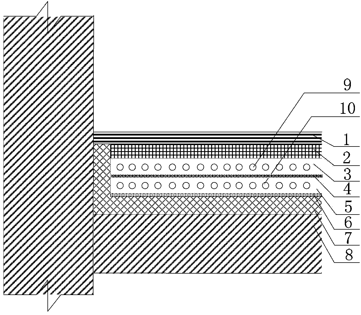
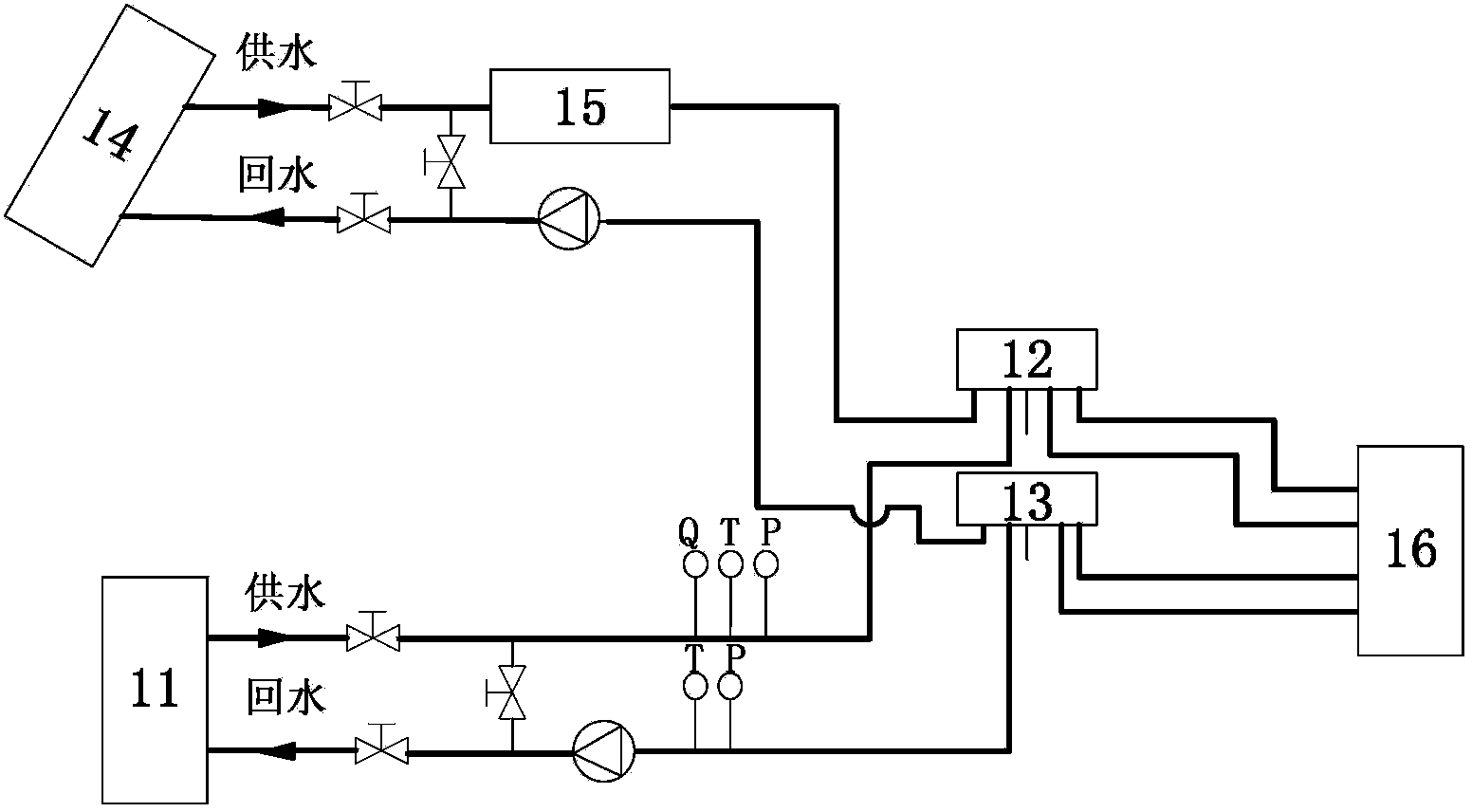
[0032] The cold and hot integrated double-layer capillary phase change energy storage floor terminal device and application system of the present invention, such as figure 1 As shown, the flow chart of the system is as follows figure 2 Shown, describe in detail below in conjunction with accompanying drawing.

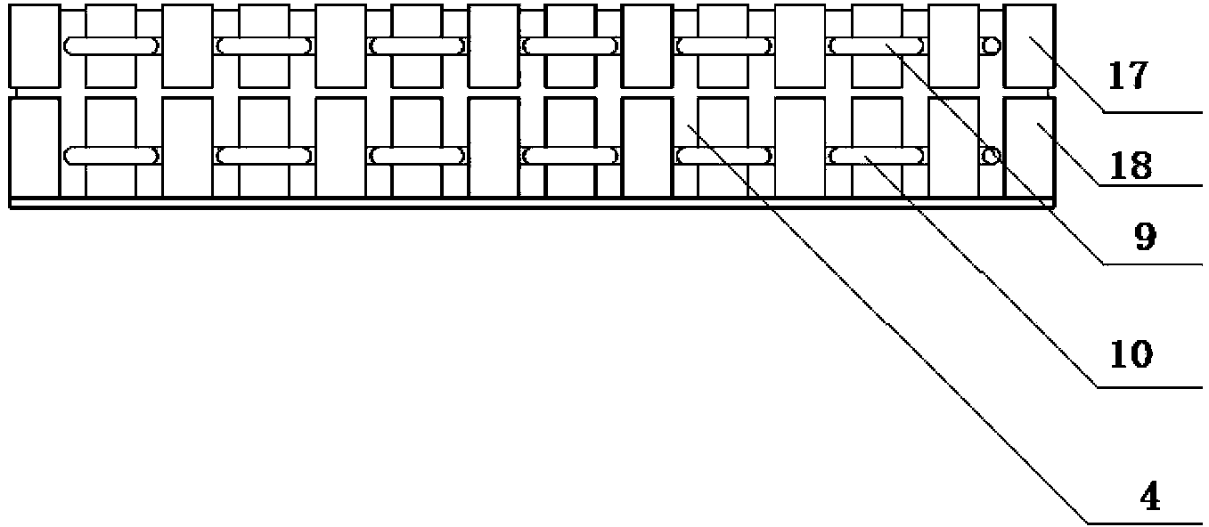
[0033] See Figure 1 to Figure 5 Each layer of the floor of the device from top to bottom is the floor surface layer 1, the concrete layer 2, the thermal storage phase change material layer 3, the cement mortar leveling layer 4, the cold storage phase change material layer 5, the reflective film 6, the thermal insulation layer 7 and the Floor structure layer 8. The phase change material is packaged in a strip-shaped metal, and a layer of cement mortar leveling layer 4 is laid between the thermal storage phase change material layer 3 and the cold storage phase change material layer 5, which not only solves the problem of state change during the phase change process, bu...


PUM


Abstract

The invention relates to a cooling-heating-integrated double-capillary-tube-layer phase-change energy storage floor terminal device and an application system. The cooling-heating-integrated device combining a traditional capillary tube radiant cooling / heating with the phase-change energy storage technology comprises a ground source heat pump, a water distributor, a water collector, a solar heat collector, an auxiliary electric heater and an energy storage floor. The energy storage floor comprises a floor surface layer, a concrete layer, a heat storage phase-change material layer, a cement mortar screeding layer, a cool storage phase-change material layer, a reflecting film and an insulating layer from top to bottom, wherein the heat storage phase-change material layer is used for storing heat at night in winter, the cement mortar screeding layer is used for separating the heat storage phase-change material layer from the cool storage phase-change material layer and facilitates laying of the phase-change material layers, the cool storage phase-change material layer is used for storing cool at night in summer, the reflecting film is used for reflecting and blocking heat to decrease heat exchange between the cool storage phase-change material layer and the insulating layer, and the insulating layer is made of materials low in heat conductivity and small in density and used for further decreasing heat loss of floor structural layers. Capillary tubes are laid in the heat storage phase-change material layer and the cool storage phase-change material layer to be used for supplying hot water and cool water respectively.

Description

technical field [0001] The invention is an integrated terminal device and an application system that combines traditional capillary radiation cooling / warming and phase change energy storage technology, and belongs to the field of building heating and air-conditioning new technologies, and the field of building energy optimization utilization and energy storage technology . In particular, it relates to the structural design of a novel energy storage floor. Background technique [0002] Floor radiant cooling / heating has been developed to this day, no matter from theoretical research or engineering practical application, it is constantly maturing and has achieved great development. Capillary floor radiation system, as a new type of air conditioning with low-temperature hot water and high-temperature cold water, can better create a comfortable environment, improve indoor air quality, and conform to the development direction of energy conservation. Moreover, with the continuous...

Claims


Application Information

Patent Timeline
Patent Type & Authority Applications(China)
IPC IPC(8): F24D15/02F24D19/00E04F15/00
Inventor 姚文超张小松夏燚刘贝张如意汪峰
Owner 东南大学常州研究院
Why Eureka
Try Eureka