Layered high-frequency fine vibrating screen

A technology of high-frequency vibration and high-frequency sieve, applied in the direction of filter screen, solid separation, grid, etc., can solve the problems of inconvenient, low processing capacity, adjustment of amplitude and frequency, etc., to improve processing capacity and improve screening Efficiency and the effect of improving the excitation force

Inactive Publication Date: 2014-11-19
HUNAN ZHAOSHENG MINING MACHINERY
View PDF8 Cites 9 Cited by
  • Summary
  • Abstract
  • Description
  • Claims
  • Application Information

AI Technical Summary

Problems solved by technology

[0010] The disadvantage is: because the slurry pump enters the slurry tank with strong turbulent flow, the slurry surface is not level, and the forced slurry distributor cannot really achieve even distribution of the slurry, resulting in unreasonable slurry distribution and cannot fully utilize the high-frequency sieve. surface processing capacity; the double-tube vibrator cannot easily adjust the amplitude and frequency, so that the processing capacity and screening efficiency of the slurry cannot be adjusted conveniently, and the imported cylindrical vibrator is expensive, and the domestic quality is not good; although The current high-frequency fine sieve has the function of making pulp again, but the effect is not good. The effect of only adding flushing water to the first transitional settlement section is not ideal, which affects the screening effect of the second section of the screen surface; the processing capacity per unit area and unit time is not good. high

Method used


Image

  • Layered high-frequency fine vibrating screen
  • Layered high-frequency fine vibrating screen
  • Layered high-frequency fine vibrating screen

Examples


Embodiment Construction

[0031] The present invention will be further described below in conjunction with accompanying drawing.

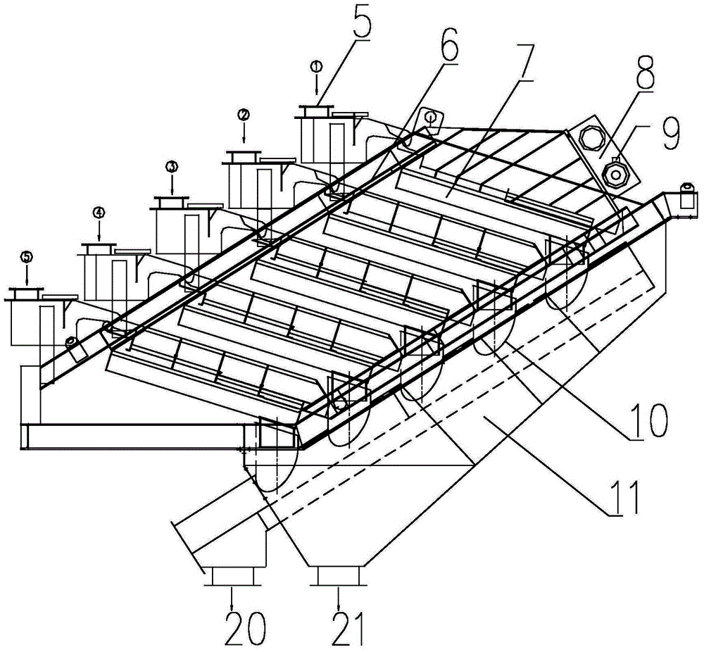
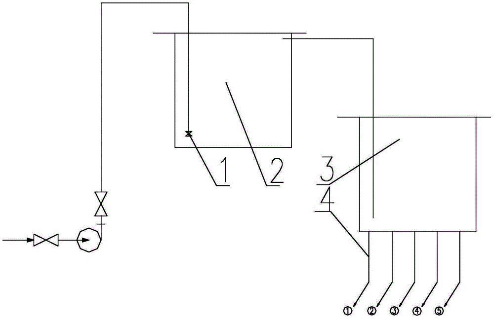
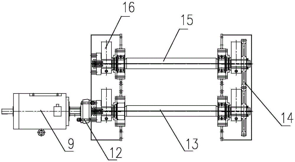
[0032] Laminated high-frequency vibrating fine screen consists of slurry distribution system, screening system and discharge system, see figure 2 , the structure of the pulp distribution system is: the feed end of the primary pulp tank 2 is connected with a porous energy dissipation valve 1, the porous energy dissipation valve 1 dissipates the energy of the pulp from the pump pool, and the overflow of the primary pulp tank 2 The mouth is connected with a secondary slurry storage tank 3, and the lower part of the secondary slurry storage tank 3 is evenly opened in a ring shape. The number of openings is equal to the number of layers of the high-frequency screen assembly 7 of the screening system. Each opening There is a hopper 5 attached; see figure 1 , image 3 , Figure 4 and Figure 5 , the screening system is composed of an excitation unit, a classification unit and...


PUM


Abstract

The invention discloses a layered high-frequency fine vibrating screen. The layered high-frequency fine vibrating screen is composed of an ore pulp distribution system, a screening system and a discharging system. The ore pulp distribution system structurally comprises a first-level ore pulp tank (2), a second-level ore pulp tank (3) and hoppers (5), wherein the feed end of the first-level ore pulp tank (2) is connected with a multihole energy dissipation valve (1); an overflow port of the first-level ore pulp tank (2) is connected with the second-level ore pulp tank (3); the hoppers (5) are connected to the lower portion of the second-level ore pulp tank (3). The screening system is composed of a vibration excitation unit, a classifying unit and a supporting unit. The discharging system has the functions of collection and discharge of materials below the screen and collection and discharge of materials on the screen, wherein the materials below all layers of high-frequency screen assemblies (7) are connected with upper chutes (10) through short pipes; the upper chutes (10) are connected with a material-below-screen main outlet (20); the materials on all the layers of high-frequency screen assemblies (7) are connected with lower chutes (11); a subsidiary discharge port (21) is connected to the lower chutes (11). The layered high-frequency fine vibrating screen has the advantages of being uniform in ore pulp feeding, high in screening efficiency and processing capacity and capable of adapting to different working conditions.

Description

technical field [0001] The invention relates to a fine screening device for fine-grained materials, in particular to a laminated high-frequency vibrating fine screen. Background technique [0002] At present, the wet classification equipment for fine-grained materials in the industry mainly includes spiral classifiers, hydrocyclones and high-frequency vibrating fine screens. The characteristics of the above-mentioned classification equipment are as follows: [0003] (1) Spiral classifier: The spiral classifier is often used in conjunction with the ball mill. The lower end of the inclined tank is the slurry classification and settlement area. The spiral rotates at a low speed to stir the pulp, and the light and fine particles are suspended above and flow to the overflow side weir. The overflow at the place enters the next process for processing, while the coarse and heavy particles settle to the bottom of the tank, and are conveyed to the discharge port by the screw to be dis...

Claims


Application Information

Patent Timeline
Patent Type & Authority Applications(China)
IPC IPC(8): B07B1/28B07B1/46
Inventor 欧明兴罗跃平王万奇李华清
Owner HUNAN ZHAOSHENG MINING MACHINERY
Why Eureka
Try Eureka