Double-rotor grinding and polishing tool used in cooperation with robot

A technique for polishing tools and robots, applied in grinding/polishing equipment, grinding/polishing safety devices, manufacturing tools, etc., can solve problems such as troublesome maintenance, easy wear of the intake pipe, wear of the air pipe, etc., and achieve simple maintenance and transmission Stable efficiency and increased service life

Pending Publication Date: 2022-07-29
SHANGHAI INST OF OPTICS & FINE MECHANICS CHINESE ACAD OF SCI
View PDF6 Cites 1 Cited by
  • Summary
  • Abstract
  • Description
  • Claims
  • Application Information

AI Technical Summary

Problems solved by technology

When the revolution and rotation are turned on at the same time, the cross universal joint must not only rotate itself, but also follow the revolution, which not only accelerates wear, but also when the revolution eccentricity is too large, the transmission efficiency of the cross universal joint is greatly reduced, and the transmission to the rotation axis Problems such as insufficient torque and torque accumulation are prone to occur, so that the removal amount is unstable during processing
The air pressure applied by the top air intake has two disadvantages. The first is that the intake pipe is easy to wear and tear. The intake pipe passes through the middle of the cross universal joint to provide pressure for the rotation axis, and the cross universal joint drives When the rotation axis rotates, there will be great wear and tear on the air pipe, which needs to be checked and replaced regularly
The second is the cylinder piston of the rotation axis. Because the cylinder piston does not rotate, but the rotation axis rotates, long-term wear will cause the rubber ring of the cylinder piston to wear, the compressed air will leak, and the pressure will decrease, resulting in Unstable removal during the process
In addition, the rubber ring of the cylinder piston is worn, and the whole mechanism needs to be disassembled for maintenance, which is troublesome to maintain

Method used


Image

  • Double-rotor grinding and polishing tool used in cooperation with robot
  • Double-rotor grinding and polishing tool used in cooperation with robot

Examples


Embodiment Construction

[0017] In order to better present the technical solutions and potential of the present invention, combined with figure 1 , figure 2 Specific embodiments are described. This section presents a typical embodiment of the present invention, and the optimization of the embodiment according to the characteristics and requirements of the dual-rotor grinding and polishing tool belongs to the protection scope of the present invention.

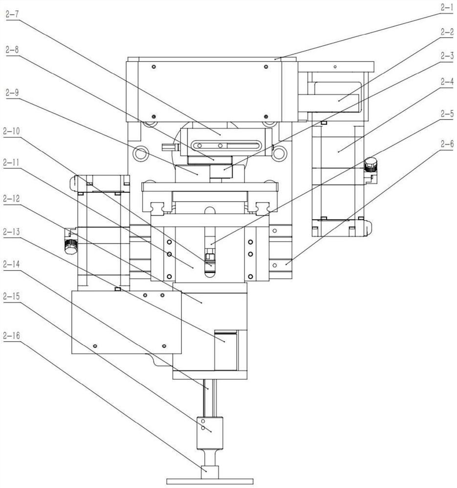
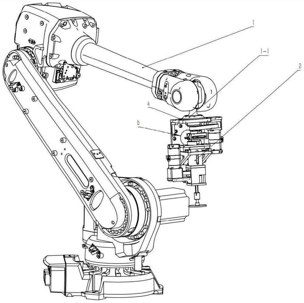
[0018] see first figure 1 , figure 2 , figure 1 It is a schematic diagram of the overall structure of the dual-rotor grinding and polishing tool used with the robot in the present invention, figure 2 It is a schematic diagram of the double-rotor grinding and polishing device used with the robot. It can be seen from the figure that the present invention is equipped with a double-rotor grinding and polishing tool used by the robot, including the robot 1, the robot end flange 1-1 and the double-rotor grinding and polishing tool head 2. The double r...


PUM


Abstract

A double-rotor grinding and polishing tool equipped with a robot for use comprises a robot body and a double-rotor grinding and polishing tool head. The double-rotor grinding and polishing tool head comprises a tool head connecting and fixing flange plate, a servo motor, a synchronous belt wheel, a telescopic air cylinder, a linear guide rail, an angular contact ball bearing, a dovetail groove sliding table, a revolution shaft, a rotation shaft, a revolution flange connecting seat, a revolution sliding support, a rotation shaft connecting seat, a rotation bearing seat, a grinding and polishing disc connecting chuck and a grinding and polishing disc. Grinding, polishing and high-precision shape modification of the optical element can be completed, the adopted robot is relatively simple in structure, stable in control performance, low in cost, flexible and suitable for multi-station machining, machining elements do not need to be moved frequently, and the surface shape and the machining period of the surface of the optical element are improved.

Description

technical field [0001] The invention relates to optical processing, in particular to a double-rotor grinding and polishing tool used with a robot. Background technique [0002] Double-rotor grinding and polishing tools play an indispensable role in modern optical processing, and play an important role in the grinding and polishing of plane, spherical, aspherical and free-form surfaces. With the development of the high-precision and complex control system of the robot, the construction of the processing equipment can be completed simply and quickly by carrying a tool head at the end of the robot. At the same time, compared with the traditional gantry type CNC small grinding head machine tool, the robot has the advantages of high degree of freedom and low cost. A double-rotor grinding and polishing tool head is installed at the end of the robot, and the removal of the workpiece surface material is controlled by calculating the residence time of the polishing disc on the workp...

Claims


Application Information

Patent Timeline
Patent Type & Authority Applications(China)
IPC IPC(8): B24B13/00B24B41/04B24B45/00B24B55/00
CPCB24B13/00B24B41/04B24B45/003B24B55/00
Inventor 江国昌魏朝阳胡晨万嵩林牛振岐
Owner SHANGHAI INST OF OPTICS & FINE MECHANICS CHINESE ACAD OF SCI
Why Eureka
Try Eureka