Cutter system for numerically-controlled cutting bed

A technology of cutting knife and cutting machine, applied in the field of cutting knife system, can solve the problems of increasing the friction frequency between the blade and the cloth, increasing the reciprocating frequency of the blade, and the working ability of the equipment is not strong, so as to eliminate the unbalanced force, increase the noise and Vibration, vibration and noise reduction effects

Pending Publication Date: 2020-03-06
WUHAN KEPUYINENG TECH CO LTD
View PDF14 Cites 1 Cited by
  • Summary
  • Abstract
  • Description
  • Claims
  • Application Information

AI Technical Summary

Problems solved by technology

[0003] The cutting machine currently used in the market is not capable of working because the eccentric spindle eccentric radius is less than or equal to 12.5mm. When the cloth to be cut is thick or hard and needs a certain cutting speed, it is necessary to increase the speed of the rotating mechanism. , thus increasing the reciprocating frequency of the blade, increasing the friction frequency between the blade and the cloth, and making the cloth stick

Method used


Image

  • Cutter system for numerically-controlled cutting bed
  • Cutter system for numerically-controlled cutting bed
  • Cutter system for numerically-controlled cutting bed

Examples


Embodiment 1

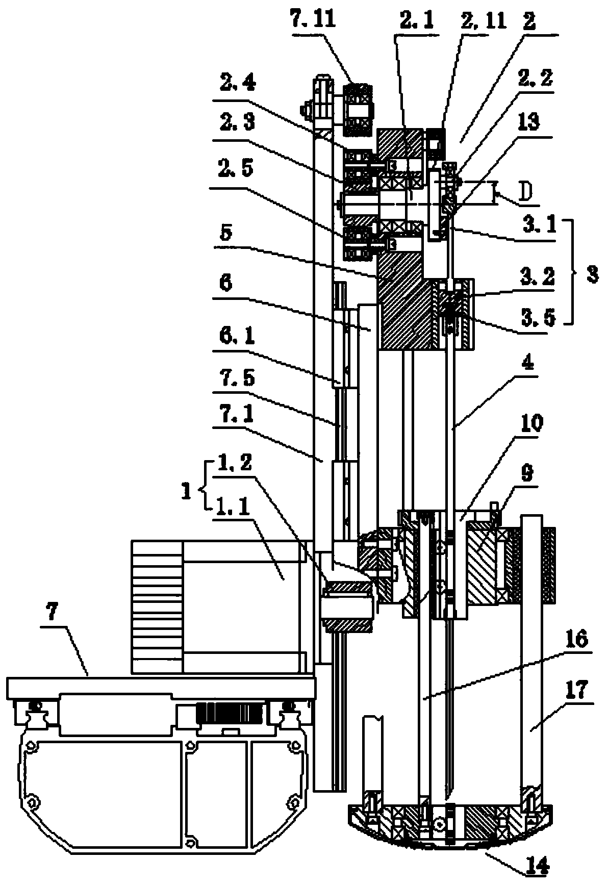
[0084] As a preferred example of the present invention, such as Figure 1 to Figure 4 As shown, the present embodiment provides a cutting knife system for a CNC cutting machine, including a power mechanism 1 and an eccentric wheel mechanism 2, and the power mechanism 1 and the eccentric wheel mechanism 2 are connected in transmission;

[0085] Such as figure 1 , Figure 4 and Figure 7 As shown, the eccentric wheel mechanism 2 includes an eccentric shaft, on which a balance wheel device 12 is arranged, and the balance wheel device 12 is connected to the eccentric shaft through transmission. The eccentric shaft includes an eccentric main shaft 2.1, and an eccentric inertial shaft 2.2 for socketing the connecting rod assembly 3 is provided on the end face of the power output end of the eccentric main shaft 2.1. The eccentric distance D between the eccentric main shaft 2.1 and the eccentric inertial shaft 2.2 is 15- 30mm, the eccentric main shaft 2.1 is provided with a first c...

Embodiment 2

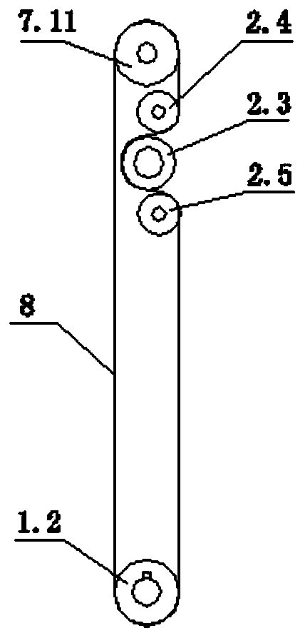
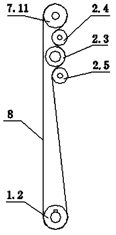
[0102] Such as Figure 5 and Figure 6 As shown, the structure of this embodiment is similar to that of Embodiment 1, and the difference is that the power mechanism 1 and the eccentric wheel mechanism 2 are relatively fixedly arranged, and the first main shaft wheel 2.3 of the power mechanism 1 and the eccentric wheel mechanism 2 are engaged by gears or Connected by conveyor belt drive.

[0103]The power mechanism 1 is a main shaft motor 1.1, and the eccentric main shaft 2.1 of the eccentric wheel mechanism 2 is fixed on the main shaft mounting seat 5 through bearings, and the main shaft mounting seat 5 is connected with the vertical frame 7.1 arranged above the CNC cutting machine through the slide plate 6 Sliding connection; specifically, the linear slider (not shown) provided on the side of the slide plate 6 facing the vertical frame 7.1 is matched with the linear guide rail (not shown) provided on the side of the vertical frame 7.1 facing the slide plate 6 slide. The ma...

Embodiment 3

[0107] The structure of this embodiment is similar to Embodiment 1, the difference is that the structure of the balance wheel device 12 is different, such as Figure 12 and Figure 13 As shown, the balance wheel device 12 includes two balance wheels 12.1, the two balance wheels 12.1 are symmetrically arranged on the left and right sides of the axis line of the eccentric main shaft 2.1, and the two balance wheels 12.1 are arranged on the main shaft mounting seat 5 On the side close to the power output end of the eccentric main shaft 2.1 (that is, the side where the main shaft mounting seat 5 is away from the vertical frame), the two balance wheels 12.1 are in transmission connection with the second main shaft wheel 2.11 provided at the power output end of the eccentric main shaft 2.1; A second tensioning wheel 12.4 is provided above one balance wheel 12.1, and the second tensioning wheel 12.4 is fixedly arranged on the main shaft mounting base 5. The second tensioning wheel 12....


PUM


Abstract

The invention discloses a cutter system for a numerically-controlled cutting bed. The cutter system comprises a spindle mounting seat, an eccentric mechanism is arranged on the spindle mounting seat and connected with a cutter through a connecting rod component, and a blade of the cutter corresponds to a cutter disc below the spindle mounting seat. By increase of an eccentric distance, the rotating speed is controlled in a certain range, increasing of the rotating speed of a motor is avoided, and accordingly reciprocating frequency of the blade is reduced, and cloth adhesion is avoided; further, by transmission connection between an eccentric shaft with a first counterweight and a balance wheel device, increasing of noise and vibration due to increasing of unbalance force can be avoided. In addition, by virtue of a disc locking device, full-automatic disc locking can be realized without manual participation; by withdrawing of a follow-up air cylinder, a certain space between the lockedcutter disc and cloth can be reserved, and in cutting operation of the numerically-controlled cutting bed, problems of twisting, turning and the like caused by the fact that the locked cutter disc drives the cloth to turn up can be avoided, so that cutting quality is improved.

Description

technical field [0001] The invention relates to the technical field of numerically controlled cutting machines, in particular to a cutting knife system for numerically controlled cutting machines. Background technique [0002] CNC cutting bed is a kind of sewing equipment used to automatically cut fabrics. It is widely used in the garment manufacturing industry. It uses the data set by the computer to control the movement trajectory of the cutter (that is, the cutting trajectory), and then cut out the required cut pieces. The cutting bed mainly includes a cutting table, a cutting knife, a fixed knife mechanism, a rotating mechanism, an operation panel, and a vacuum suction device; In the fixed knife mechanism, the fixed knife mechanism is connected with the rotating mechanism, so that the cutter can complete various curves or straight lines. [0003] The cutting machine currently used in the market is less than or equal to 12.5mm in the eccentric radius of the eccentric sp...

Claims


Application Information

Patent Timeline
Patent Type & Authority Applications(China)
IPC IPC(8): D06H7/00
CPCD06H7/00
Inventor 张晓东
Owner WUHAN KEPUYINENG TECH CO LTD
Why Eureka
Try Eureka