Sliding bearing plate sintering method and supporting frame used in method

A technology for sliding bearings and plates, which is applied in the sintering method of sliding bearing plates and the support used in the method, which can solve the problems of inability to ensure the heat distribution between layers and the uniformity of sintering atmosphere, reduce the performance of sintered products, and unstable sintering quality, etc. problems, to achieve the effect of increasing production quantity, improving efficiency, and reasonable structural size

Active Publication Date: 2014-11-19
嘉兴立一新材料股份有限公司
View PDF6 Cites 0 Cited by
  • Summary
  • Abstract
  • Description
  • Claims
  • Application Information

AI Technical Summary

Problems solved by technology

[0005] Due to the high environmental requirements for the sintering of sliding bearing plates, the existing technology is generally single-layer sintering. The production quantity per unit time of this method is low, and it cannot reach a high processing capacity in a short time. In order to improve efficiency, some manufacturers I came up with a method of using galvanized steel sheets as isolation layers between layers of copper-plated metal sheets to achieve multi-layer sintering. However, due to the close combination of sliding bearing sheets and galvanized steel sheets during the sintering process, it is impossible to ensure the heat between layers. The distribution and uniformity of the sintering atmosphere, thereby reducing the performance of the sintered product, basically cannot be applied
[0006] Therefore, it is urgent to invent a device for sintering of multi-layer sliding bearing plates to solve the problems of low sintering efficiency and unstable sintering quality of existing sliding bearing plates

Method used


Image

  • Sliding bearing plate sintering method and supporting frame used in method
  • Sliding bearing plate sintering method and supporting frame used in method
  • Sliding bearing plate sintering method and supporting frame used in method

Examples


Embodiment 1

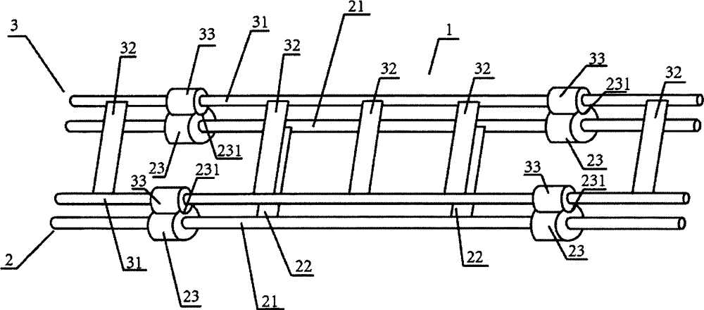
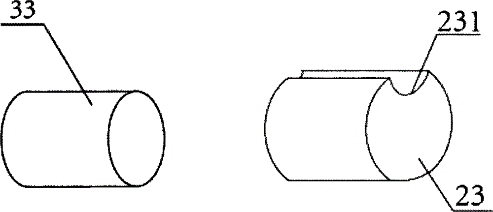
[0050] See attached Figure 1-2 , a support 1 for sliding bearing plate sintering, including an A discharge layer 2 and a B discharge layer 3; the A discharge layer 2 includes two support rods 21 and two connecting rods 22; the two support rods Both ends are covered with fixing pieces 23; all fixing pieces are in the shape of a cylinder, and the surface is provided with a concave surface 231 with an opening upward; the B discharging layer 3 includes two support rods 31 and five connecting rods 32; all Both ends of the support rod are covered with fixing parts 33; all the fixing parts are in the shape of a cylinder; all the fixing parts can be correspondingly snapped into the concave surface 231; among the five connecting rods, three connecting rods are located at the fixing parts at both ends of the supporting rod Between, there is a connecting rod between one fixing part and the end point of the support rod close to the fixing part, and there is a connecting rod between the o...

Embodiment 2

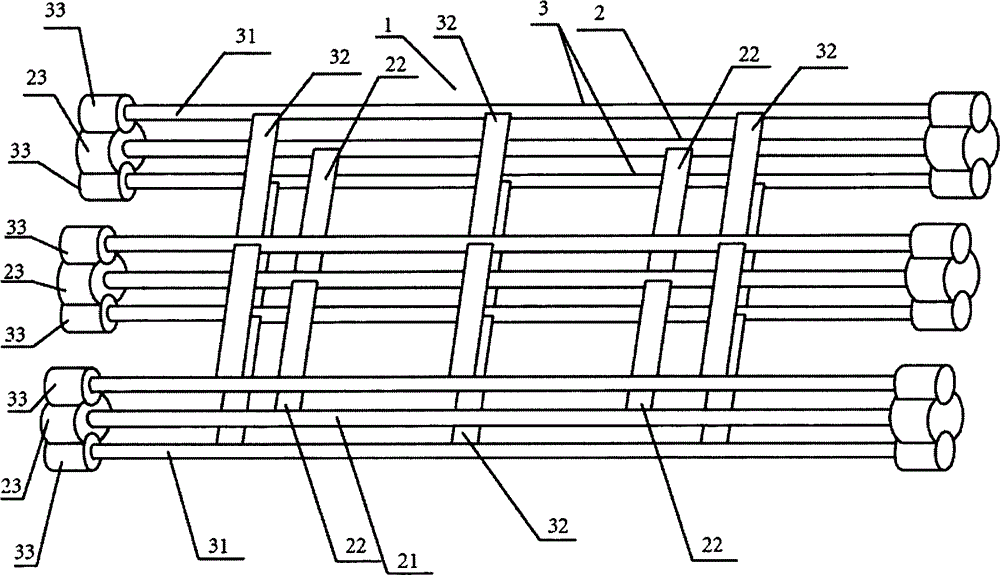
[0053] See attached Figure 3-4 , a support 1 for sliding bearing plate sintering, including an A discharge layer 2 and a B discharge layer 3; the A discharge layer 2 includes three support rods 21 and four connecting rods 22; both ends of all support rods are Covered with fixing parts 23; all fixing parts are in the shape of a cylinder, and the surface is provided with a concave surface 231 with an opening facing upward and a concave surface 232 with an opening facing downward; the B discharging layer 3 includes three support rods 31 and six connecting rods 32; Both ends of all support rods are covered with fixing parts 33; all fixing parts are in the shape of a cylinder; all fixing parts can be snapped into the corresponding concave surface 231 and concave surface 232;

[0054] The support rod is connected to the connecting rod by welding; the total number of layers of the discharge layer is 3 layers, and the A discharge layer is located between the two B discharge layers; t...

Embodiment 3

[0056] See attached Figure 5-6 , a support 1 for sliding bearing plate sintering, including an A discharge layer 2 and a B discharge layer 3; the A discharge layer 2 includes three connecting rods 22 and two support rods 21; the two support rods 21 Both ends are covered with fixing parts 23; all fixing parts are in the shape of a cylinder, and its surface is provided with a concave surface 232 with an opening facing down; A winding knot 221 and a winding knot 222 are formed on the rod; the winding knot 221 and the winding knot 222 are respectively in contact with the support rods of the B discharge layer; among the three connecting rods, one connecting rod is located between the fixing parts at both ends of the supporting rod, and one The connecting rod is located between one fixing part and the end point of the supporting rod close to the fixing part, and one connecting rod is located between the other fixing part and the end point of the supporting rod close to the fixing p...


PUM

PropertyMeasurementUnit
areaaaaaaaaaaa
areaaaaaaaaaaa
areaaaaaaaaaaa

Abstract

The invention discloses a sliding bearing plate sintering method and a supporting frame used in the method. The supporting frame comprises discharging layers A and discharging layers B. Each discharging layer A comprises a supporting rod and a connecting rod, wherein fixing parts are arranged at the two ends of the supporting rod and are regularly stereoscopic; each discharging layer B comprises a supporting rod and a connecting rod, wherein the supporting rod is connected with the connecting rod, and fixing parts are arranged at the two ends of the supporting rod and are regularly stereoscopic; the fixing parts of the discharging layers B can be clamped into the fixing parts of the discharging layers A, the discharging layers A and the discharging layers B are overlapped, and the total layer number of the discharging layers is 2-12. According to the sliding bearing plates sintered through the supporting frame, the performance of plates and the performance of parts of each plate are consistent, and the problems that the plate in the prior art is low in sintering efficiency and unstable in sintering quality are successfully resolved.

Description

technical field [0001] The invention relates to a metal sintering method, in particular to a sliding bearing plate sintering method and a bracket used in the method. Background technique [0002] Sliding bearing plates are used for the production and processing of sliding bearings, based on metal plates sintered with copper alloy powder. The sliding bearing plate has the characteristics of high load capacity, impact resistance, high temperature resistance, strong self-lubricating ability, corrosion resistance, etc. The products made of sliding bearing plate are especially suitable for heavy load, low speed, reciprocating or swinging, etc., which are difficult to lubricate and form oil film It is mainly used in the production of boundary lubricated bearings, oil-free lubricated bearings and bimetallic bearings. At present, the products have been widely used in construction machinery, automobiles, plastic molding machinery, hydraulic components, logistics port machinery, punc...

Claims


Application Information

Patent Timeline
Patent Type & Authority Applications(China)
IPC IPC(8): B22F3/10
Inventor 韩建宋晓静
Owner 嘉兴立一新材料股份有限公司
Why Eureka
Try Eureka