A super RO membrane device and a zero-discharge method for reclaimed water reuse using the device
A water inlet chamber and membrane technology, applied in chemical instruments and methods, water/sewage multi-stage treatment, water/sludge/sewage treatment, etc., can solve the problem of high operating costs, high energy consumption of thermal concentration, and unbearable factories and other issues to achieve the effects of avoiding emissions, improving economic benefits, reducing scale and operating costs
- Summary
- Abstract
- Description
- Claims
- Application Information
AI Technical Summary
Problems solved by technology
Method used
Image
Examples
Embodiment 1
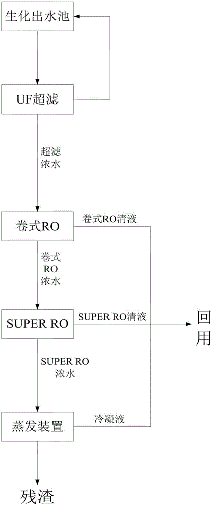
[0040] Such as figure 1 As shown, the zero-discharge technology for reclaimed water reuse is equipped with a biochemical effluent tank for holding biochemical effluent, and UF ultrafiltration devices, roll-type RO membrane devices, SUPER RO membrane devices, and evaporation devices are also arranged in sequence on the biochemical effluent tanks. , A clear water pool is also provided to connect with the roll-type RO membrane device, SUPER RO membrane device and evaporation device.
[0041] The biochemical effluent is exported from the biochemical effluent pool. After the macromolecular pollutants are filtered by the UF ultrafiltration device, the produced water cycle enters the biochemical effluent pool again, and the ultrafiltration concentrated water obtained after filtration enters the roll-type RO membrane device for the next step of concentration. .
[0042] The ultrafiltration concentrated water is divided into two parts after being concentrated by the roll-type RO membr...
Embodiment 2
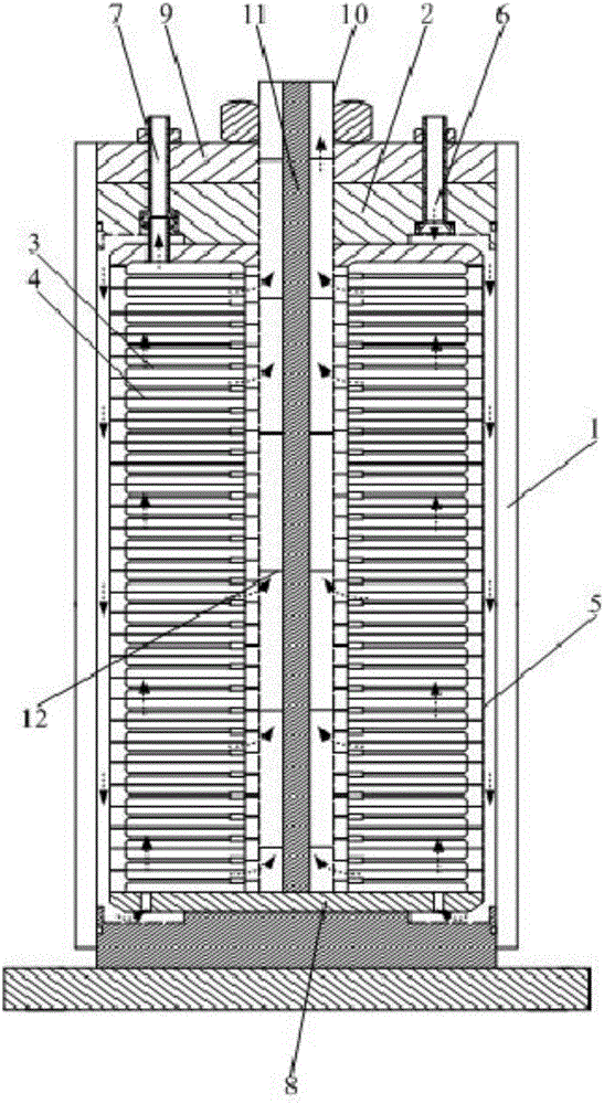
[0048] Such as figure 2 , 3 As shown in , 9, a SUPER RO membrane device includes a circular tube pressure-bearing shell 1, metal sealing sheets 9 and flanges are respectively arranged at the upper and lower ends of the circular tube pressure-bearing shell 1, and the pressure-bearing The upper and lower ends of the shell 1 are respectively provided with a fluid reverse disc 2 adjacent to the metal sealing sheet 9 and the flange, and a sealed circular disc is also provided between the circular tube pressure-bearing shell 1 and the two fluid reverse discs 2. Tube pressure-bearing inner shell 5, inside the sealed round tube pressure-bearing inner shell 5, there are also supporting deflectors 3 and diaphragms 4, and a water distributor is also set at the lower end of the sealed round tube pressure-bearing inner shell 5 8. In the central position of the water distributor 8, there is also an inner tie rod that runs through and supports the deflector plate 3, the diaphragm 4, the up...
Embodiment 3
[0054] Such as Figure 4 , 5As shown, the difference between this embodiment and Embodiment 1 lies in that the bosses are convex strips 39 , and the convex strips 39 are arranged on both sides of the deflector plate 3 in a certain arc in sequence. The convex line 39 can better guide the dirty liquid, further reduce the pressure loss of the dirty liquid in the flow process, make better use of production resources, and reduce production loss; at the same time, the convex line 39 and the diaphragm 4 The contact area is larger, which further reduces the force on the surface of the diaphragm 4, better avoids the damage of the diaphragm 4 during use, improves the service life of the diaphragm 4, and reduces the maintenance frequency during use. Greatly improved the use effect.
PUM
| Property | Measurement | Unit |
|---|---|---|
| thickness | aaaaa | aaaaa |
Abstract
Description
Claims
Application Information
 - R&D
- Intellectual Property
- Life Sciences
- Materials
- Tech Scout
- Unparalleled Data Quality
- Higher Quality Content
- 60% Fewer Hallucinations
Browse by: Latest US Patents, China's latest patents, Technical Efficacy Thesaurus, Application Domain, Technology Topic, Popular Technical Reports.
© 2025 PatSnap. All rights reserved.Legal|Privacy policy|Modern Slavery Act Transparency Statement|Sitemap|About US| Contact US: help@patsnap.com


