Blocking controlling and leaking stopping tool assembly and leaking stopping method applied to drilling engineering

A tool assembly and drilling engineering technology, applied in wellbore/well components, earthmoving, sealing/packing, etc., can solve problems such as difficulty in degassing, decrease in cement plug strength, reverse flow into the wellbore, etc. The process is simple and practical, the effect of ensuring accuracy and improving the success rate

Inactive Publication Date: 2014-11-19
SICHUAN HAYWARD PETROLEUM ENG TECH
View PDF5 Cites 8 Cited by
  • Summary
  • Abstract
  • Description
  • Claims
  • Application Information

AI Technical Summary

Problems solved by technology

[0007] 2. In order to prevent the cement slurry of the drilling tool from staying in the drilling tool or the drilling tool is fixed by cement or the drilling tool is in a static state for a long time, the drill may be stuck. Therefore, after the slurry is replaced, the drilling tool must be lifted to Therefore, there are two problems: (1) Due to the pressure surge when pulling out the drill, at this time, under the influence of the pressure surge, the formation fluid will flow into the wellbore in reverse, thus affecting the compressive strength of the cement sheath; ( 2) When the drilling tool is pulled out, the volume in the wellbore decreases, and the reduced volume must be supplemented by formation fluid, which will also cause the strength of the cement ring plug to decrease;
[0009] 4. Once hollowing occurs in the drilling tool, during the grouting process, due to the high viscosity

Method used


Image

  • Blocking controlling and leaking stopping tool assembly and leaking stopping method applied to drilling engineering
  • Blocking controlling and leaking stopping tool assembly and leaking stopping method applied to drilling engineering
  • Blocking controlling and leaking stopping tool assembly and leaking stopping method applied to drilling engineering

Examples


Embodiment Construction

[0046] Below in conjunction with accompanying drawing, the present invention is described in further detail:

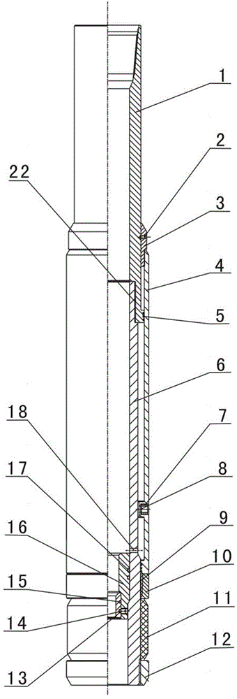
[0047] Such as Figure 1-Figure 4 As shown, the plugging control and plugging tool assembly used in drilling engineering according to the present invention includes an inner cylinder 6, a cylinder liner 4, a locking ring 9, a locking sleeve 10, a sealing rubber sleeve 11, an end seat 12, a rubber plug Seat 16, ball seat 13, ball 19, front rubber plug 20 and rear rubber plug 21, wherein:

[0048] Let the axial direction of the inner tube 6 be the up-down direction, the cylinder liner 4 is set outside the inner tube 6 and can move in the up-down direction, the upper end of the inner tube 6 and the upper end of the cylinder liner 4 are open and used to connect the drill pipe shown), the end seat 12 is set on the lower end of the inner cylinder 6 by screwing, the sealing rubber tube 11 with pressure expansion and expansion performance is set on the outside of the inner c...


PUM


Abstract

The invention discloses a blocking controlling and leaking stopping tool assembly applied to drilling engineering. The blocking controlling and leaking stopping tool assembly comprises an inner barrel, a cylinder sleeve, a locking ring, a locking sleeve, a sealing and separating glue barrel, an end base, a rubber plug base, a ball seat, a ball, a front rubber plug and a back rubber plug, wherein the ball seat is matched with the ball, and the rubber plug base is matched with the front rubber plug and the back rubber plug. The inner barrel is sleeved with the cylinder sleeve which can move. The end base is arranged at the lower end of the inner barrel in a sleeved mode. The sealing and separating glue barrel is arranged between the locking sleeve and the end base. The cylinder sleeve is arranged above the locking sleeve. Circulating holes are formed in the inner barrel. The invention further discloses a method for stopping well drilling leaking through the blocking controlling and leaking stopping tool assembly. The method comprises the following steps that the blocking controlling and leaking stopping tool assembly is placed downwards to a well; the ball is thrown to the needed position to increase the pressure, and the sealing and separating glue barrel is used for sealing in a sitting mode; heavy mud is recycled; the front rubber plug is pressed to the needed position, and water and mud injection is carried out; the back rubber plug is pressed to the needed position; the mud is replaced; the pressure is increased to knock down the ball seat; the mud is continuously replaced until the back rubber plug makes contact with the front rubber plug; mud replacing is stopped, and the tool assembly is pulled out of the hole; cement setting is carried out, and leaking stopping is finished. When the tool assembly is used for stopping leaking of the well, annulus mud and formation fluid cannot be mixed into cement paste, pollution is not produced during waiting on cement stopping, and the setting strength of a cement sheath plug is high.

Description

technical field [0001] The invention relates to a plugging device and a plugging method in drilling engineering, in particular to a plugging control and plugging tool assembly and a plugging method used in drilling engineering. Background technique [0002] In the process of oil drilling, when the drill bit uncovers cracks, caves, faults and other formations in high-permeability and low-pressure formations and limestone formations, if the liquid column pressure of the well fluid is higher than the formation pressure, lost circulation will occur. Lost circulation is a common downhole complex situation in the drilling process. For formations with well-developed fractures and fractured zone formations of faults, vicious lost circulation will occur. In very serious lost circulation, the hydrostatic surface in the wellbore is far away from the ground. The drop of the liquid level is determined according to the vertical depth of the lost zone, the hydrostatic head of the lost zone...

Claims


Application Information

Patent Timeline
IPC IPC(8): E21B33/13
Inventor 卢长生刘兆康
Owner SICHUAN HAYWARD PETROLEUM ENG TECH
Why Eureka
Try Eureka