Double-flow-state clean combustion boiler and double-flow-state clean combustion technology

A clean combustion and fluidized technology, applied in the direction of burning fuel in the molten state, fluidized bed combustion equipment, combustion method, etc., can solve the problem of reducing the proportion of fine particles in the bed inventory, increasing the amount of fine particles, and the difference in fluidization wind speed. And other issues

Active Publication Date: 2015-04-15
刘学冰
View PDF6 Cites 0 Cited by
  • Summary
  • Abstract
  • Description
  • Claims
  • Application Information

AI Technical Summary

Problems solved by technology

After the fluid state is reconstructed, the amount of coarse particles constituting the non-circulating bed material at the bottom is greatly reduced, the amount of fine particles constituting the fast bed increases slightly, the total bed inventory is greatly reduced and the proportion of fine particles is greatly increased. The proportion of coal is determined by the coal type, the particle size of the coal into the furnace and the structure of the boiler itself, and it is difficult to truly realize the theoretical requirements during implementation.
[0008] The particle size of circulating bed boiler fuel has wide screening characteristics, generally 0mm--13mm, and narrower ones are also 0-8mm. The particle size is generally distributed according to the normal curve, and the fluidization wind speed corresponding to different particle sizes varies greatly. There are only relatively fixed flue gas flow rates at different heights in the furnace of circulating bed boilers, which is not conducive to controlling the fluidization quality of materials with wide screening particle sizes

Method used


Image

  • Double-flow-state clean combustion boiler and double-flow-state clean combustion technology
  • Double-flow-state clean combustion boiler and double-flow-state clean combustion technology

Examples


Embodiment 2

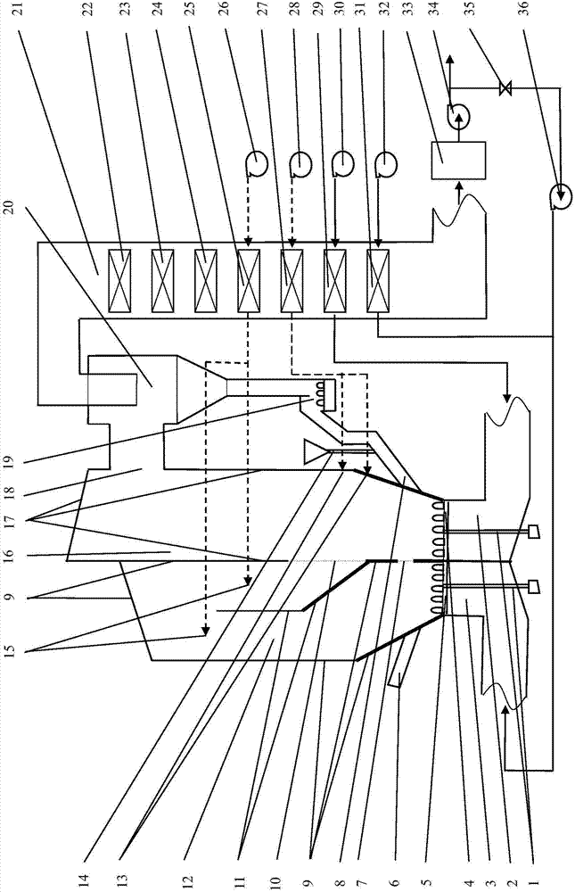
[0065] Embodiment two, such as figure 2 Shown:

[0066] The specific structure and composition of the bubbling bed and the circulating bed are basically the same as those in Example 1, the difference is that the source of the primary air, optionally, the bubbling fluidized bed (bubbling bed for short) is respectively provided with a second A primary air flue gas fan 36 and a second primary air fan 32, and a second primary air air preheater 31 is arranged at the outlet air duct of the second primary air fan 32. The flue gas volume, air volume and primary air volume of the bubbling bed are adjusted by fan speed regulation.

[0067] Similarly, the bubbling bed secondary air can be separately provided with a bubbling bed secondary fan 26 or / and a bubbling bed secondary air air preheater 25 .

[0068] Likewise, in the bubbling bed furnace, the secondary tuyeres 15 of the bubbling bed furnace can be arranged in multiple layers or / and in multiple points. The style of the tuyere c...


PUM


Abstract

The invention discloses a double-flow-state clean combustion boiler and a double-flow-state clean combustion technology. The boiler comprises a bubbling fluidized bed and a circulating fluidized bed, wherein an overflow port and a first window are formed between a circulating fluidized bed firebox and a bubbling fluidized bed firebox; air distribution plates and primary air chambers are arranged at the bottoms of the circulating fluidized bed and the bubbling fluidized bed; a circulating fluidized bed smoke outlet is connected with a cyclone separator, a return feeder and a return leg in sequence, and then connected to the lower part of the circulating fluidized bed firebox and a tail flue connected with a smoke outlet of the cyclone separator; at least one set of bubbling fluidized bed is arranged on the side surface of the circulating fluidized bed firebox. Under a condition of using the same fuel particles, the clean combustion boiler can decompose and adjust the parameters that possibly conflict in the adjusting process of indexes, so that the indexes can be optimized to the utmost extent through adjustment of a single parameter or a few parameters (such as primary air volume, secondary air volume and oxygen content).

Description

technical field [0001] The invention relates to the optimized clean combustion of a circulating bed boiler, in particular to the technical field of a dual-flow circulating fluidized bed boiler. Background technique [0002] Circulating bed (also known as circulating fluidized bed) combustion technology has the characteristics of cleanliness, environmental protection, and wide adaptability to coal types. It has been widely valued by countries all over the world. It has developed rapidly in the past two decades and is currently the most commercialized. Clean coal combustion technology. [0003] The advantages of clean coal combustion in circulating bed boilers lie in low-temperature combustion and staged combustion: the furnace temperature is only about 900°C; oxygen-deficient combustion is maintained at the bottom of the furnace to control the formation of nitrogen oxides and achieve low-nitrogen combustion; Secondary air supplements oxygen to enhance combustion and improve ...

Claims


Application Information

Patent Timeline
Patent Type & Authority Patents(China)
IPC IPC(8): F23C10/06F23C10/18
Inventor 刘学冰
Owner 刘学冰
Why Eureka
Try Eureka