Steel ball surface spreading apparatus based on machine vision

A technology of machine vision and steel ball, which is applied in the direction of measuring devices, instruments, scientific instruments, etc., can solve the problem that the steel ball cannot be rolled and unfolded actively, and achieve the effects of easy layout and adjustment, high sorting efficiency, and avoiding missed inspections

Active Publication Date: 2014-11-19
NINGBO BAIJIABAI MEASUREMENT & CONTROL EQUIP
View PDF9 Cites 7 Cited by
  • Summary
  • Abstract
  • Description
  • Claims
  • Application Information

AI Technical Summary

Problems solved by technology

[0004] In view of the deficiencies in the prior art above, the purpose of the present invention is to provide a steel ball surface unfolding device for steel ball...

Method used


Image

  • Steel ball surface spreading apparatus based on machine vision
  • Steel ball surface spreading apparatus based on machine vision
  • Steel ball surface spreading apparatus based on machine vision

Examples


Embodiment 1

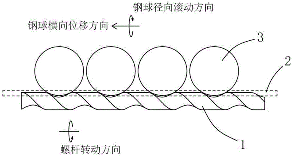
[0023] Example 1, see figure 1 Shown:

[0024] A steel ball surface unfolding device based on machine vision. This device is an important component of a steel ball sorter, including a guide rail 2 for carrying steel balls 3, and a screw 1 arranged under the guide rail 2 and rolling with the steel balls 3. And the driving device that drives the screw rod 1 to rotate (the driving device and the screw rod 1 can adopt connection structures such as gears and belts, which belong to known technology, so the driving device is not shown in the figure), the screw rod 1 is provided with a spiral groove that matches the bottom of the steel ball 3, The pitches of the spiral grooves are equal. When the steel ball 3 passes through the guide rail 2 above the screw 1, the steel ball 3 rolls radially and laterally displaces relative to the guide rail 2 under the joint action of the drive of the screw 1 and the guidance of the guide rail 2, and the steel ball 3Roll radially at least one circle....

Embodiment 2

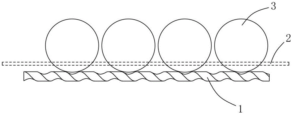
[0030] Example 2, see figure 2 Shown:

[0031] In this embodiment, the surface expansion of the steel ball 3 with a ball diameter of 36 mm is used as an example for illustration, wherein the length of the screw 1 is 180 mm, and the length of the pitch is 20 mm, that is, the length of the screw 1 is 9 times the pitch, and the screw 1 rotates for 2 turns to drive the steel ball. The ball 3 radially rolls 1 / 4 of the circle relative to the guide rail 2 and displaces 2 pitches laterally. The difference between this embodiment and Embodiment 1 is that the ball diameter of the steel ball 3 is greater than 1 times the pitch of the screw 1 but less than 2 times the pitch. Under the action, only after the screw rod 1 rotates for 2 weeks, the next steel ball 3 has space to enter the spiral groove from the front end of the screw rod 1 again. This embodiment shows that: when the ball diameter of the steel ball 3 is greater than N times the pitch but less than N+1 times the pitch, N≥0, t...

Embodiment 3

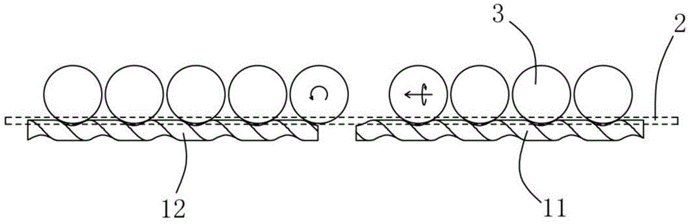
[0032] Example 3, see image 3 with Figure 4 Shown:

[0033] Embodiment 1 and Embodiment 2 both use a screw rod 1 to drive the steel ball 3, and the image sensor can only pick up an image that goes around the steel ball 3 in one rolling direction, while the image sensor has Therefore, the surface image of the entire steel ball 3 cannot be fully captured. To solve this problem, two images can be added at the position where the steel ball 3 exits from the front end of the screw 1 and the position where the steel ball 3 exits from the rear end of the screw 1. The steel ball 3 at two positions rolls along the guide rail 2, and has a nearly orthogonal angle with the radial rolling of the screw 1, so the image sensor can capture the images of the steel ball 3 at six positions to reconstruct and generate a complete steel ball 3. Image of the surface of the ball 3. However, there is still a certain degree of randomness in the two captured images added by this method, which will af...


PUM


Abstract

The invention discloses a steel ball surface spreading apparatus based on machine vision. The steel ball surface spreading apparatus comprises guide rails used for bearing steel balls, a screw which is parallely arranged below the guide rails and is in rolling fit with the steel balls and a drive unit driving the screw to rotate. When the steel balls pass through the guide rails above the screw, the steel balls carry out radial rolling and lateral displacement relative to the guide rails under driving of the screw and guiding of the guide rails, and the steel balls carry out radial rolling at least for one circle. According to the invention, the technical means of driving by the screw is employed for passive rolling spreading of the steel balls to mainly overcome the technical problem that active rolling spreading of two adjacent steel balls cannot be realized due to close contact of the two adjacent steel balls; intact surface images of steel balls can be shot, leak detection is avoided, a false drop rate is reduced and is 0.0001 to 0.0002, sorting efficiency is high, and the steel ball surface spreading apparatus is applicable to industrial batch sorting of steel balls.

Description

technical field [0001] The invention relates to the technical field of steel ball sorting equipment, in particular to a steel ball surface spreading device of the steel ball sorting equipment. Background technique [0002] Machine vision is to use machines instead of human eyes for measurement and judgment. Machine vision technology refers to converting the captured target into an image signal through machine vision products (ie, image capture device, which is divided into CMOS and CCD) and transmitting it to a dedicated image. The processing system converts the information into digital signals according to pixel distribution, brightness, color and other information; the image system performs various calculations on these signals to extract the characteristics of the target, and then controls the on-site equipment actions according to the results of the discrimination. [0003] The surface defect detection of bearing steel balls based on machine vision technology is currentl...

Claims


Application Information

Patent Timeline
IPC IPC(8): G01N21/892B07C5/342
Inventor 李方
Owner NINGBO BAIJIABAI MEASUREMENT & CONTROL EQUIP
Why Eureka
Try Eureka