A kind of glass tube vacuum packaging method of traveling wave tube cathode

A technology of vacuum packaging and traveling wave tube, applied in cold cathode manufacturing, discharge tube/lamp manufacturing, electrode system manufacturing, etc., can solve the problems of prolonging cathode time, reducing the vacuum degree of the whole tube, and reducing the service life of the whole tube, etc. To achieve the effect of ensuring performance and meeting the needs of preparation

Active Publication Date: 2016-08-24
HUADONG PHOTOELECTRIC TECHN INST OF ANHUI PROVINCE
View PDF6 Cites 0 Cited by
  • Summary
  • Abstract
  • Description
  • Claims
  • Application Information

AI Technical Summary

Problems solved by technology

The main factors affecting the cathode poisoning resistance are oxygen and water vapor in the environment, and it is difficult to ensure the continuity of the process during the cathode preparation process, which prolongs the time for the cathode to be exposed to the atmosphere, which is likely to cause the oxidation of cathode parts and active substances. Damp phenomenon
The oxidized parts adsorb a large amount of gas, and the adsorbed gas can be separated out again in the vacuum state inside the traveling wave tube, which becomes the source of outgassing, which reduces the vacuum degree of the whole tube and easily causes cathode poisoning; affects the normality of the cathode Working or not working properly, greatly reducing the service life of the whole tube
[0003] The cathode matrix of conventional barium tungsten cathodes is usually made of pure tungsten. When metal tungsten encounters water vapor, a water cycle reaction occurs, which also makes it difficult for the cathode to activate and emit normally. The active material impregnated in the cathode tungsten sponge is also very easy to absorb water vapor. Water vapor cannot be eliminated during aging, which also causes cathode poisoning, which in turn affects the performance of the traveling wave tube

Method used


Image

  • A kind of glass tube vacuum packaging method of traveling wave tube cathode
  • A kind of glass tube vacuum packaging method of traveling wave tube cathode
  • A kind of glass tube vacuum packaging method of traveling wave tube cathode

Examples


Embodiment Construction

[0030] The specific implementation manner of the present invention will be described in further detail below by describing the best embodiment with reference to the accompanying drawings.

[0031] The glass tube vacuum packaging method of the traveling wave tube cathode comprises the following steps;

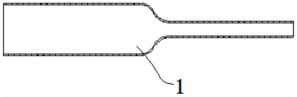
[0032] (1) Take a glass tube 1 with a large end and a small end, preheat and dry;

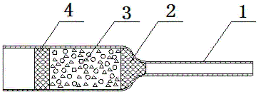
[0033] (2) Put the protective net, cathode component or active material 3 into the large end of the glass tube 1, and the two sides of the cathode component or active material 3 are respectively fixed by the protective net;

[0034] (3) Seal the end face of the big end of glass tube 1 under the protection of protective gas;

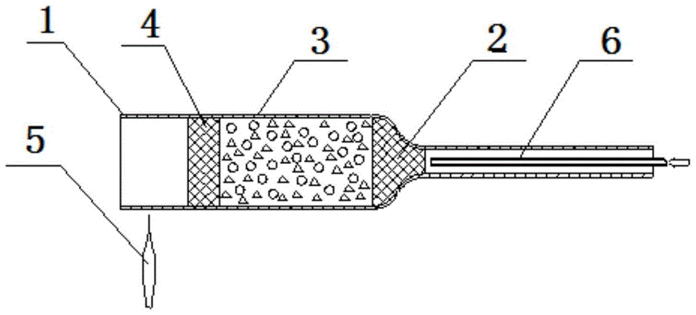
[0035] (4) Encapsulate the small end of the glass tube 1 on a vacuum exhaust table, and carry out vacuum treatment;

[0036] (5) Seal the glass tube 1 on the vacuum exhaust table 8 to complete the vacuum packaging of the glass tube 1 to the cathode component or the active ...


PUM


Abstract

The invention discloses a glass tube vacuum packaging method for traveling wave tube cathode, comprising the following steps: (1) taking a glass tube with a large end and a small end, preheating and drying; (2) placing protective nets, cathode components or active substances in Into the big end of the glass tube, the cathode part or the active material are fixed on both sides by protective nets respectively; (3) The end face of the big end of the glass tube is closed under the protection of the protective gas; (4) The small end of the glass tube is sealed with a vacuum exhaust (5) seal off the glass tube on the vacuum exhaust stage to complete the vacuum packaging of the cathode component or active material by the glass tube; the present invention carries out vacuum packaging for the cathode component or active material, The cathode parts or active materials are isolated from the outside world, to prevent the cathode parts or active materials from being affected by external factors, to ensure the performance of the cathode parts or active materials, to further ensure the performance of the traveling wave tube, and to meet the preparation needs of the cathode of the traveling wave tube.

Description

technical field [0001] The invention relates to the field of manufacturing cathodes of traveling wave tubes in microwave vacuum devices, in particular to a glass tube vacuum packaging method for the cathodes of traveling wave tubes. Background technique [0002] The cathode is a key component that affects the life of the traveling wave tube. When manufacturing the cathode, it is necessary to fully consider the importance of poisoning resistance to the performance of the cathode. The main factors affecting the cathode poisoning resistance are oxygen and water vapor in the environment, and it is difficult to ensure the continuity of the process during the cathode preparation process, which prolongs the time for the cathode to be exposed to the atmosphere, which is likely to cause the oxidation of cathode parts and active substances. damp phenomenon. The oxidized parts adsorb a large amount of gas, and the adsorbed gas can be separated out again in the vacuum state inside the ...

Claims


Application Information

Patent Timeline
Patent Type & Authority Patents(China)
IPC IPC(8): H01J9/02
Inventor 孟昭红陈爱民于晨晨卞磊王莹
Owner HUADONG PHOTOELECTRIC TECHN INST OF ANHUI PROVINCE
Why Eureka
Try Eureka