A clamp drive circuit
A driving circuit and clamping technology, applied in electrical components, output power conversion devices, etc., can solve the problems of high manufacturing process dependence, high power loss, large current, etc., to achieve low process dependence and reduce circuit power consumption. Effect
- Summary
- Abstract
- Description
- Claims
- Application Information
AI Technical Summary
Problems solved by technology
Method used
Image
Examples
Embodiment Construction
[0025] Below in conjunction with the drawings, preferred embodiments of the present invention are given and described in detail.
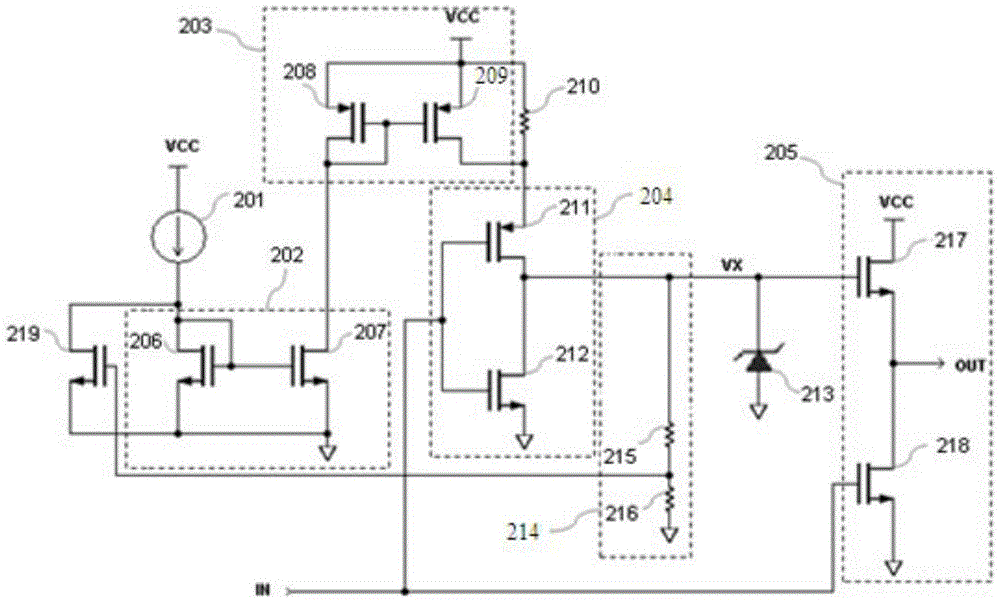
[0026] Such as figure 1 As shown, the present invention, that is, an embodiment of a clamping drive circuit includes: a power supply VCC, a bias current source 201, a switching current mirror 202, an accelerating current mirror 203, an inverter 204, a totem pole output driver 205, a stabilizing Voltage maintaining resistor 210, internal clamping device 213, clamping sampling circuit 214, and current mirror switch tube 219, specifically:
[0027] The input end of the bias current source 201 is connected to the power supply VCC, and its output end is connected to the input end of the conversion current mirror 202;
[0028] The conversion current mirror 202 includes a first MOS transistor 206 and a second MOS transistor 207, wherein the drain of the first MOS transistor 206 is respectively connected to its gate and the output end of the bias current ...
PUM
 Abstract
Description
Claims
Application Information
 - R&D
- Intellectual Property
- Life Sciences
- Materials
- Tech Scout
- Unparalleled Data Quality
- Higher Quality Content
- 60% Fewer Hallucinations
Browse by: Latest US Patents, China's latest patents, Technical Efficacy Thesaurus, Application Domain, Technology Topic, Popular Technical Reports.
© 2025 PatSnap. All rights reserved.Legal|Privacy policy|Modern Slavery Act Transparency Statement|Sitemap|About US| Contact US: help@patsnap.com


