Ripple filter circuit and method

A filter circuit and filter capacitor technology, applied in the field of electronics, can solve the problems of high cost of low-pass ripple filtering and inability to integrate large capacitors, so as to reduce the cost of circuit preparation and realize the effect of integrated chip design.

Active Publication Date: 2014-11-19
SILERGY SEMICON TECH (HANGZHOU) CO LTD
View PDF3 Cites 11 Cited by
  • Summary
  • Abstract
  • Description
  • Claims
  • Application Information

AI Technical Summary

Problems solved by technology

But in fact, large capacitors such as 100nF cannot be integrated in the chip, and generally can only be realized by discrete devices outside the chip, resulting in a high cost of low-pass ripple filtering

Method used


Image

  • Ripple filter circuit and method
  • Ripple filter circuit and method
  • Ripple filter circuit and method

Examples


Embodiment 1

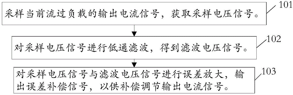
[0059] figure 1 Refer to the figure for a schematic flowchart of a filtering method provided in this embodiment. The method mainly includes:

[0060] Step 101: Sampling and acquiring a sampling voltage signal, which can represent an output current signal currently flowing through the load.

[0061] A sampling circuit is provided to acquire a sampling voltage signal that can represent the output current signal currently flowing through the load.

[0062] For the implementation of the sampling circuit, please refer to but not limited to Embodiment 2 and figure 2 , 3 shown, and will not be described here.

[0063] Step 102: Filter the sampled voltage signal to obtain a filtered voltage signal.

[0064] A filtering circuit is connected to the output end of the sampling circuit to filter the sampling voltage signal. The filter circuit in this embodiment is composed of a switched capacitor circuit controlled by a clock signal and a filter capacitor. Among them, the switched ...

Embodiment 2

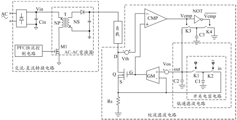
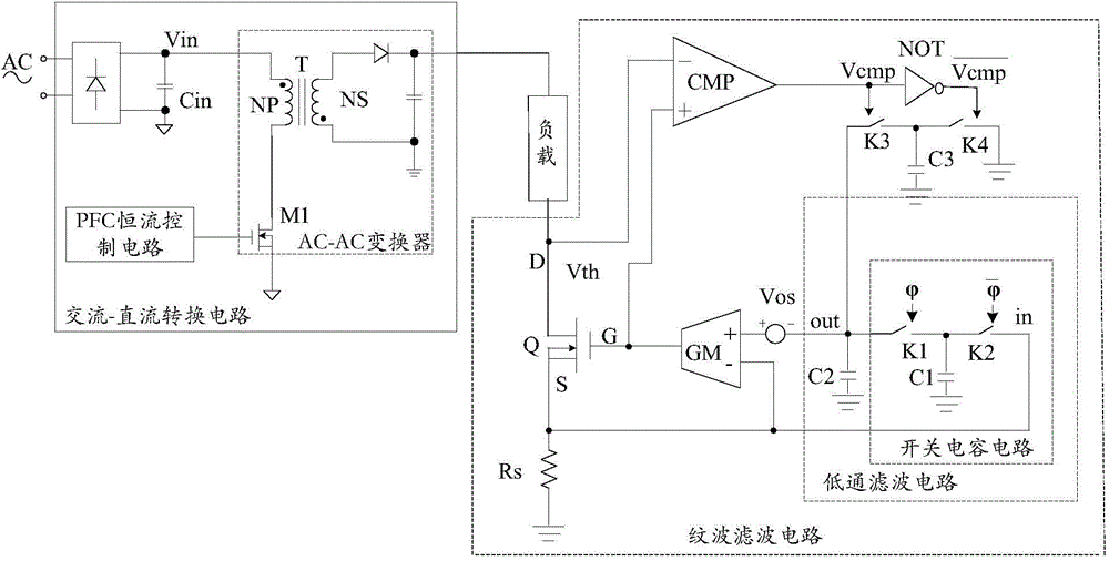
[0074] figure 2 , 3 The schematic diagrams are respectively the specific implementation circuit structures of the two ripple filter circuits provided in this embodiment.

[0075] see figure 2 , 3 As shown, it mainly includes: sampling circuit, filter circuit and error amplifier circuit.

[0076] Wherein, the sampling circuit is used for sampling and acquiring a sampling voltage signal that can be used to characterize the output current signal currently flowing through the load.

[0077] The filter circuit is composed of a switched capacitor circuit controlled by a clock signal and a filter capacitor, where the switched capacitor circuit is equivalent to Figure 4 The resistor R in the shown traditional RC filter circuit and the filter capacitor C2 form a filter circuit equivalent to the traditional RC low-pass filter circuit. The input end of the filter circuit is connected to the output end of the sampling circuit, and the filter circuit filters the input sampling volt...

Embodiment 3

[0095] Figure 6 It is a schematic diagram of a specific implementation circuit structure of a ripple filter circuit provided in this embodiment.

[0096] see Figure 6 As shown, the circuit of this embodiment is the same as that in Embodiment 2 figure 2 The main differences in the circuit shown are:

[0097] Example 2 figure 2 The ripple filter circuit is used to adjust the power of the filter capacitor C2 according to the voltage difference between the gate and the drain of the power switch tube Q. The circuit mainly includes: a first comparator CMP1, a third switch K3 and a third capacitor C3.

[0098] The circuit for adjusting the power of the filter capacitor C2 according to the voltage difference between the gate and the drain of the power switch tube Q in the ripple filter circuit of this embodiment mainly includes: a second comparator CMP2, a fifth switch K5 and Current source I1.

[0099] The first input terminal of the second comparator CMP2 (such as Figure...


PUM


Abstract

The invention discloses a ripple filter circuit and a method. The circuit comprises a sampling circuit, a lowpass filter circuit and an error amplifying circuit. The sampling circuit obtains a sampling voltage signal representing an output current signal flowing through a load at present through sampling; the input end of the lowpass filter circuit is connected with the output end of the sampling circuit, the lowpass filter circuit is formed by a switched capacitor circuit and a filter capacitor, and the switched capacitor circuit is controlled through a clock signal; a first input end of the error amplifying circuit is connected with the output end of the sampling circuit, a second input end of the error amplifying circuit is connected with the output end of the lowpass filter circuit, and the output end of the error amplifying circuit outputs an error compensation signal. By the adoption of the technical scheme, improvement of integrated design of the chip is facilitated, and circuit cost is reduced.

Description

technical field [0001] The invention relates to the field of electronics, in particular to a ripple filter circuit and method. Background technique [0002] The AC-DC driving circuit in the prior art mainly rectifies and converts the input AC power into a half-sine wave DC power by using a rectifier bridge, and then generates and outputs a DC current signal through a power stage circuit controlled by a PFC constant current control circuit. [0003] The DC current signal output of the AC-DC drive circuit generally has power frequency ripple. If the DC current signal with power frequency ripple is directly supplied to the load during application, it will affect the service life of the load. For example, in In the LED drive circuit, the power frequency ripple will cause the load to flicker, which will affect the use and cause damage to the life of the LED. [0004] Therefore, it is necessary to perform ripple processing on the DC current signal output by the AC-DC drive circui...

Claims


Application Information

Patent Timeline
Patent Type & Authority Applications(China)
IPC IPC(8): H02M1/15
Inventor 金津赖洪斌
Owner SILERGY SEMICON TECH (HANGZHOU) CO LTD
Why Eureka
Try Eureka