Deep-water contactless trigger switch

A non-contact, trigger switch technology, applied in the deep sea field, can solve the problems of low reliability, complicated production, long life, etc., and achieve the effect of safe and reliable work, compact structure and strong earthquake resistance

Inactive Publication Date: 2014-11-19
山东拓普液压气动有限公司
View PDF7 Cites 4 Cited by
  • Summary
  • Abstract
  • Description
  • Claims
  • Application Information

AI Technical Summary

Problems solved by technology

The Chinese patent No. 201220336210.4 discloses a single-wire non-contact limit switch, which uses technologies such as bidirectional thyristor and its trigger circuit to solve the problems of multiple wiring, complicated production, and low reliability, but still has poor versatility, Issues such as narrow scope of application
The Chinese patent No. 201220

Method used


Image

  • Deep-water contactless trigger switch
  • Deep-water contactless trigger switch
  • Deep-water contactless trigger switch

Examples


Embodiment 1

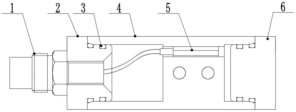
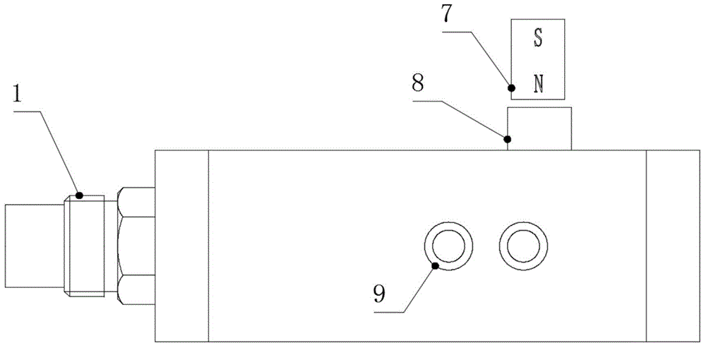
[0022] see figure 1 , this embodiment is a structural diagram of a deep-water non-contact trigger switch type I that can be used alone, including a small watertight connector 1, a front cover 2, an O-ring 3, a switch body 4, and a solid-state electronic non-contact switch element 5. The rear end cover 6; the solid-state electronic non-contact switch element 5 is sealed in the switch body 4, and the solid-state electronic non-contact switch element is equipped with a protection circuit; the front end of the switch body 4 cooperates with the front end cover 2, and the rear end of the switch body 4 Cooperating with the rear end cover 6, the O-ring 3 ensures its underwater tightness; the front end of the solid-state electronic non-contact switch element 5 is connected with the small watertight connector 1 through a connecting wire, which has strong shock resistance and shock resistance Sex, and is equipped with a protection circuit, even if it is reversed, it will not be damaged; ...

Embodiment 2

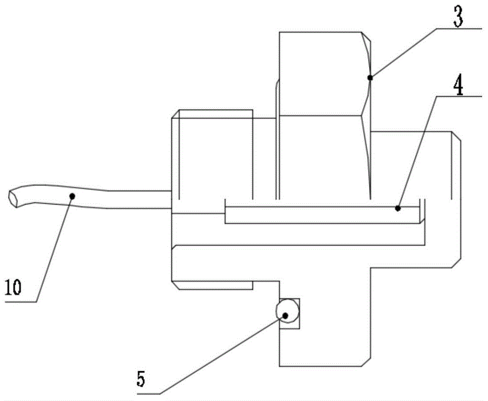
[0027] see image 3 , this embodiment is a variant of the deep-water non-contact trigger switch, that is, non-contact deep-water trigger switch type II, including an O-ring 3, a switch body 4, a solid-state electronic non-contact switch element 5, a lead wire 10, and a lead wire 10 Installed on the switch body 4, it can be directly connected with external components through the lead wire 10. Compared with the first embodiment, the type II non-contact deep-water trigger switch can be directly installed on the end cover of the deep-sea control pressure chamber without external cables, effectively solving the problem of compact structure of underwater instruments and equipment. Others are the same as embodiment one.


PUM


Abstract

The invention belongs to the field of deep-sea technologies and relates to a deep-water contactless trigger switch. The deep-water contactless trigger switch comprises a solid state electronic contactless switch element and a switch body, wherein the solid state electronic contactless switch element is sealed in the switch body. The deep-water contactless trigger switch is characterized by further comprising a small watertight connector, a front end cover, an O-shaped sealing ring, a back end cover and a magnet; axial and radial dual-seal structures are adopted on the contact place of the front end cover and the switch body and the contact place of the back end cover and the switch body, and the axial direction and the radial direction are both sealed by the O-shaped sealing rings. According to the deep-water contactless trigger switch, the problem of deep-sea high-pressure sealing is effectively solved, so that the deep-water contactless trigger switch is safe and reliable; a deep-sea small watertight connector allowing wet plugging under the water is provided for adapting to requirements of the deep-water severe environment, and the maximum working water depth is up to 14000 m; the deep-water contactless trigger switch can be applied to multilayer trawling of abyssal plankton and deep-sea detection and sampling devices, such as submarine sediment acoustics in-situ detection systems.

Description

technical field [0001] The invention belongs to the field of deep-sea technology, in particular to a deep-water non-contact trigger switch used on a deep-sea detection instrument and a sampling device. Background technique [0002] Entering the 21st century, countries around the world are developing rapidly in the field of deep-sea technology, and China has developed particularly rapidly in deep-sea technology such as deep-sea detection instruments and sampling devices. A trigger switch is needed, but most of the existing trigger switches adopt a mechanical operation mode, which has relatively large operating force, difficult operation, and low reliability. The Chinese patent No. 201220336210.4 discloses a single-wire non-contact limit switch, which uses technologies such as bidirectional thyristor and its trigger circuit to solve the problems of multiple wiring, complicated production, and low reliability, but still has poor versatility, problems such as narrow scope of ap...

Claims


Application Information

Patent Timeline
IPC IPC(8): H03K17/95
Inventor 刘敬喜季念迎刘延俊李官保阚光明韩国忠
Owner 山东拓普液压气动有限公司
Why Eureka
Try Eureka