Composite nozzle and method for producing composite fiber

A technology of composite nozzles and polymers, applied in fiber processing, textile and papermaking, spinneret assemblies, etc., can solve the problems of difficult structure, high equipment cost, complicated nozzle structure, etc., to prevent convergence and high dimensional stability. Effect

Active Publication Date: 2016-04-13
TORAY IND INC
View PDF9 Cites 0 Cited by
  • Summary
  • Abstract
  • Description
  • Claims
  • Application Information

AI Technical Summary

Problems solved by technology

According to the knowledge of the present inventors, in the pipe group of the pipe 30, it may be difficult in terms of structure to freely arrange the sea component polymer introduction channel 31
In this way, for example, in order to install in the pipeline group, it is necessary to install the sea component polymer introduction channel 31 by bending the pipeline 30 halfway, etc., so the structure of the nozzle becomes very complicated, and there is a problem that the equipment cost is too high.

Method used


Image

  • Composite nozzle and method for producing composite fiber
  • Composite nozzle and method for producing composite fiber
  • Composite nozzle and method for producing composite fiber

Examples


Embodiment 1

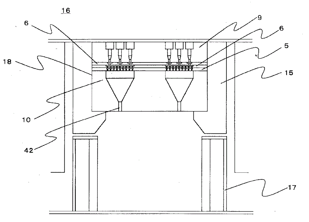
[0157] Polyethylene terephthalate (PET melt viscosity: 120 Pas) with an intrinsic viscosity (IV) of 0.63 dl / g as the island component, and 5-sulfonic acid metabolite with an IV of 0.58 dl / g as the sea component polymer Sodium phthalate 5.0 mol% copolymerized PET (melt viscosity of copolymerized PET: 140 Pas) was melted at 290°C, measured, and flowed into a Figure 6 The spin pack of the composite nozzle according to this embodiment shown discharges a sea-island composite polymer flow from the discharge hole of the nozzle. In addition, 700 island component discharge holes were perforated at equal intervals for one discharge introduction hole for the island component polymer in the distribution plate at the lowest layer. The sea-island ratio was set to 30 / 70, and oil was added to the discharged composite polymer flow after cooling and solidification, and it was wound at a spinning speed of 1500m / min, and 110dtex-15 filaments were selected (single-hole discharge capacity 2.25g / mi...

Embodiment 2

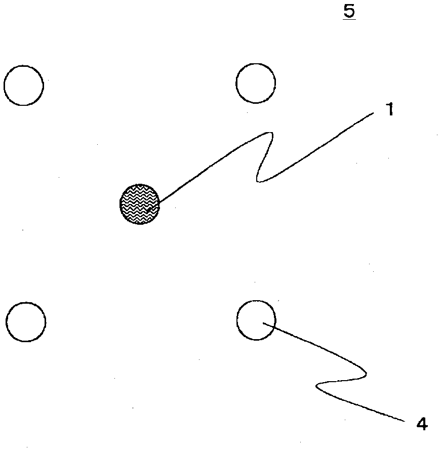
[0160] Such as figure 2 As shown, the arrangement of the island component discharge holes and the sea component discharge holes of the distribution plate on the lowermost layer is arranged in such a manner that n=4, which are the conditions of formulas (1), (2) and (3), are arranged. The same composite nozzle as in Example 1. In the distribution plate at the bottom layer, 600 island component discharge holes are perforated at equal intervals for one discharge introduction hole for the island component polymer. The sea-island ratio was set to 50 / 50, and other than that, spinning was performed with the same polymer as in Example 1, the same fineness, and spinning conditions, and 9000 multifilaments were selected. Here, in the composite nozzle used in Example 2, the island component discharge hole and the sea component discharge hole with a hole diameter of 0.2 mm have a radius R1 of 0.25 mm on the imaginary circular line C1, and a radius R2 of the imaginary circular line C2 of...

Embodiment 3

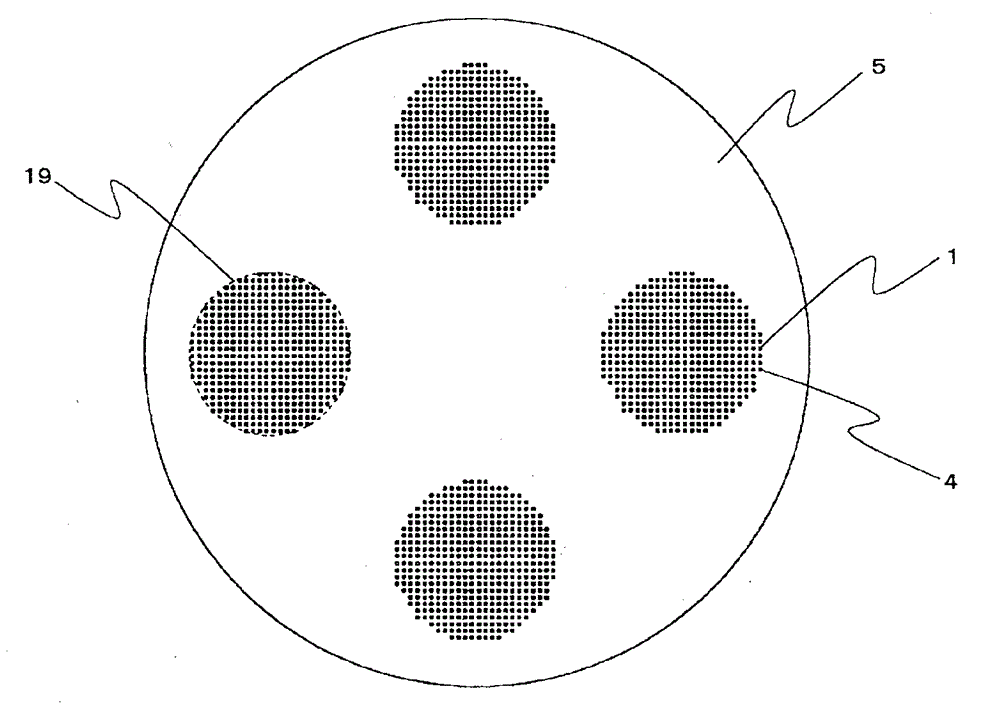
[0162] Such as image 3 As shown, the arrangement of the island component discharge holes and the sea component discharge holes of the distribution plate on the lowermost layer is arranged in such a manner that n=6, which are the conditions of formulas (1), (2) and (3), are arranged. The same composite nozzle as in Example 1. In the distribution plate of the lowest layer, 500 island component discharge holes are perforated at equal intervals for one discharge introduction hole for the island component polymer. The sea-island ratio was set to 50 / 50, and other than that, spinning was performed with the same polymer as in Example 1, the same fineness, and spinning conditions, and 7500 multifilaments were selected. Here, in the composite nozzle used in Example 3, the island component discharge hole and the sea component discharge hole with a hole diameter of 0.2 mm have a radius R1 of 0.33 mm on the imaginary circumferential line C1, and a radius R2 of the imaginary circumferenti...


PUM

PropertyMeasurementUnit
diameteraaaaaaaaaa
diameteraaaaaaaaaa
diameteraaaaaaaaaa

Abstract

Provided is a composite spinneret for discharging a composite polymer stream composed of an island component polymer and a sea component polymer, including one or more distribution plates in which distribution holes and distribution grooves for distributing the polymer components are formed; and a lowermost layer distribution plate positioned to the downstream side of the distribution plate in the direction of the polymer spinning path and provided with a plurality of island component discharge holes and a plurality of sea component discharge holes, wherein the composite spinneret has a plurality of hole groups composed of n island component discharge holes centered on a center O and arranged on a circular line C1 with a radius R1, n sea component discharge holes centered on the center O and arranged on a circular line C2 with a radius R2, n group centers P centered on the center O and arranged on a circular line C3 with a radius R3, n island component discharge holes centered on the group center P and arranged on a circular line C5 with a radius R1, and n sea component discharge holes centered on the P and arranged on a circular line C6 with a radius R2 are present; and R1, R2 and R3 satisfy the following expression (1) and (2): (1) R �¢ 1 ‰¤ R �¢ 2 €¢ cos 180 / n degree (2) R �¢ 3 = 2 €¢ R �¢ 2 and each discharge hole is arranged according to predetermined conditions.

Description

technical field [0001] The present invention relates to a composite nozzle and a method for manufacturing a composite fiber. Background technique [0002] Fibers made of thermoplastic polymers such as polyester and polyamide are excellent in mechanical properties and dimensional stability, so they are used in a variety of applications, and many fibers with various functions have been developed. [0003] For example, in the application of clothing, the following improvements have been made: for the purpose of imparting a soft feel, etc., to make the monofilament finer and multifilament, and to improve the water absorption, quick-drying, and change the gloss, etc., to make the monofilament special-shaped , or to modify (modify) the polymer in order to impart new functionality such as dyeing with excellent vividness. In addition, in the application of industrial materials, the following improvements have been made in addition to the same fineness of monofilaments, multifilamen...

Claims


Application Information

Patent Timeline
Patent Type & Authority Patents(China)
IPC IPC(8): D01D5/36D01D4/02
CPCD01D4/06D01D5/36
Inventor 船越祥二增田正人
Owner TORAY IND INC
Why Eureka
Try Eureka