Grate-type waste incinerator and method for incinerating waste

A waste and incinerator technology, applied in the field of grate-type waste incinerators, can solve the problems of shortening the life of refractories, increasing the generation of CO, and increasing harmful substances.

Active Publication Date: 2014-11-19
JFEENG CORP
View PDF5 Cites 2 Cited by
  • Summary
  • Abstract
  • Description
  • Claims
  • Application Information

AI Technical Summary

Problems solved by technology

That is, the instability of combustion of waste generated at a low air ratio causes the following problems, that is, the generation of CO is increased, the amount of NOx generated during combustion is rapidly increased due to a local increase in flame temperature, and a large amount of gas is generated. soot, thereby increasing harmful substances in the exhaust gases from grat

Method used


Image

  • Grate-type waste incinerator and method for incinerating waste
  • Grate-type waste incinerator and method for incinerating waste
  • Grate-type waste incinerator and method for incinerating waste

Examples


no. 1 Embodiment approach

[0101] Below, refer to Figure 1 to Figure 4 The grate type waste incinerator and the waste incineration method using the grate type waste incinerator according to the first embodiment of the present invention will be described.

[0102]

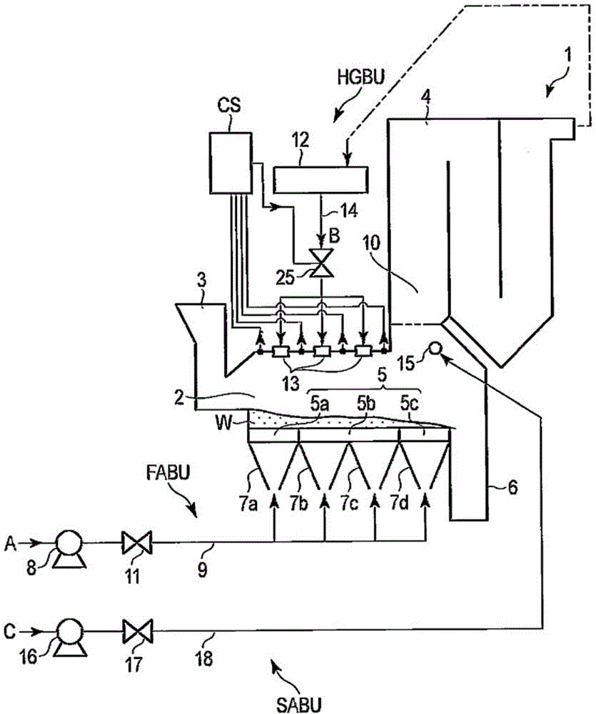
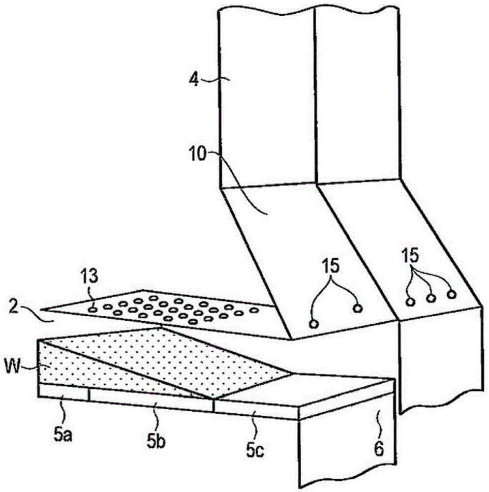
[0103] figure 1 The shown grate-type waste incinerator 1 comprises a combustion chamber 2 provided with a grate 5 onto which waste W is fed, during the movement of the fed waste W Burn this waste. The height of the combustion chamber 2 from the grate 5 to the top of the combustion chamber is in the range of 1 to 3 m, which is equivalent to the height of the combustion chamber of an existing grate-type waste incinerator with a waste incineration capacity of about 100 tons / day. Compared with about 5m~6m, it is less than or equal to 1 / 2 of its height. In addition, the volume of the combustion chamber 2 of the grate type waste incinerator 1 of this embodiment is 90 m 3 , 190m with the volume of the combustion chamber of the conventional gr...

Embodiment

[0231] Using the conventional grate type waste incinerator (comparative example) disclosed in Japanese Patent Laid-Open No. 2004-84981 (Patent Document 1) and the grate type waste incinerator (example) of this embodiment, The experiment of incinerating waste was carried out on the scale of 120 tons / day of incineration, compared the NO in the exhaust gas discharged respectively from the comparative example and the embodiment X concentration and CO concentration.

[0232] The results are shown in Table 1 below.

[0233] [Table 1]

[0234] Table 1

[0235]

[0236] As can be seen from Table 1, compared with the comparative example, in the embodiment, the furnace volume (the volume of the combustion chamber 2) can be changed to about 1 / 2, even if the air ratio is further reduced, the waste can be fully burned, and , can reduce CO, NO X and other harmful gas production.

no. 2 Embodiment approach

[0238] Next, a grate type waste incinerator according to a second embodiment of the present invention will be described.

[0239] The outline of the grate type waste incinerator according to the second embodiment is as follows.

[0240] In the grate-type waste incinerator according to the second embodiment, the appropriateness of the injection flow rate of the high-temperature gas blown downward from the top of the combustion chamber corresponding to the height of the combustion chamber from the grate to the top is clarified. The upper and lower limits of the range determine the preferred range.

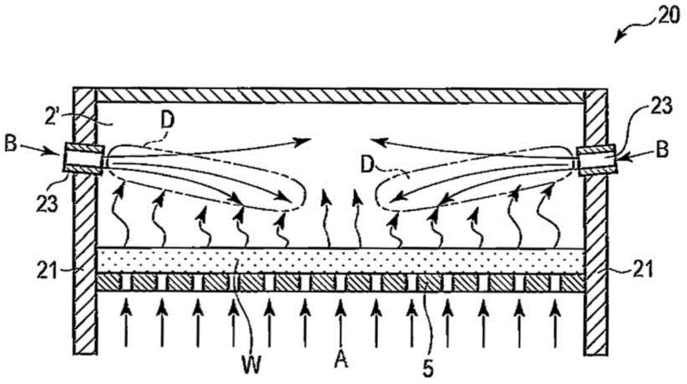
[0241] Combustion gas including combustible gas is formed above the waste on the grate by blowing hot gas downward from the top of the combustion chamber against the updraft of combustible gas containing combustible gas generated from the waste The planar combustion area can be stably formed by proper stagnation or circulation of the high-temperature gas. For this reason, it is nece...


PUM


Abstract

Provided is a grate-type waste incinerator that is capable of reducing the amount of hazardous substance generation, and performing combustion of waste with ease using a low air ratio, and a method for incinerating waste. An incinerator (1) includes a combustion chamber (2) that combusts waste (W) while the waste moves on a grate (5); a primary gas blowing unit (FABU) that blows a primary combustion gas (A) from below the grate into the combustion chamber; and a hot gas blowing unit (HGBU) that has a plurality of hot gas blowing ports (13) which blow hot gas (B) down from an upper position one to three meters away from the grate in the combustion chamber toward a predetermined site between a waste combustion initiation area and a main combustion area in the combustion chamber. The hot gas that is blown in inhibits an upward flow of the combustion gas that contains a flammable gas which is generated from the waste, and induces stagnation or circulation of the hot gas or the combustion gas for the waste on the grate to provide a stable planar combustion area for the waste.

Description

technical field [0001] The present invention relates to a grate type waste incinerator and a waste incineration method for incinerating waste such as municipal waste, for example. Background technique [0002] As an incinerator for incinerating waste such as municipal waste, a grate type waste incinerator is widely used. An outline of a representative structure of the above-mentioned grate type waste incinerator will be described below. [0003] The existing grate-type waste incinerator as described above has three stages of inclined grates (drying grate, combustion grate and post-combustion grate) arranged in the lower part of the combustion chamber for burning waste. ). The grate has a mechanism for conveying the accumulated waste. In the combustion chamber, a waste inlet is provided above the drying grate on the side opposite to the combustion grate. In addition, in the post-combustion grate, an ash drop hole is provided below the side opposite to the combustion grate...

Claims


Application Information

Patent Timeline
IPC IPC(8): F23G5/14F23G5/00F23G5/027
Inventor 傳田知广中山刚内山武岩崎敏彦植竹规人长尾厚志
Owner JFEENG CORP
Why Eureka
Try Eureka