
Expansion valve throttling structure and heat pump system containing same

A technology of expansion valve and thermal expansion valve, which is applied in the direction of fluid circulation arrangement, lighting and heating equipment, refrigeration components, etc., and can solve problems such as capillary throttling cannot be adjusted, electronic expansion valve reliability is not strong, electromagnetic interference, etc.

Inactive Publication Date: 2014-11-26
GREE ELECTRIC APPLIANCES TECH CO LTD OF ZHUHAI
View PDF7 Cites 2 Cited by
  • Summary
  • Abstract
  • Description
  • Claims
  • Application Information

AI Technical Summary

Problems solved by technology

Commonly used throttling methods include capillary tubes, electronic expansion valves, etc., but they all have different degrees of shortcomings. Capillary tube throttling has the disadvantage of being unadjustable, while electronic expansion valves have the disadvantages of low reliability, need to be driven by electricity, and have electromagnetic interference, etc. shortcoming

Method used


Image

  • Expansion valve throttling structure and heat pump system containing same
  • Expansion valve throttling structure and heat pump system containing same
  • Expansion valve throttling structure and heat pump system containing same

Examples


Embodiment Construction

[0016] The present invention will be described in further detail below in conjunction with the accompanying drawings and specific embodiments, but not as a limitation of the present invention.

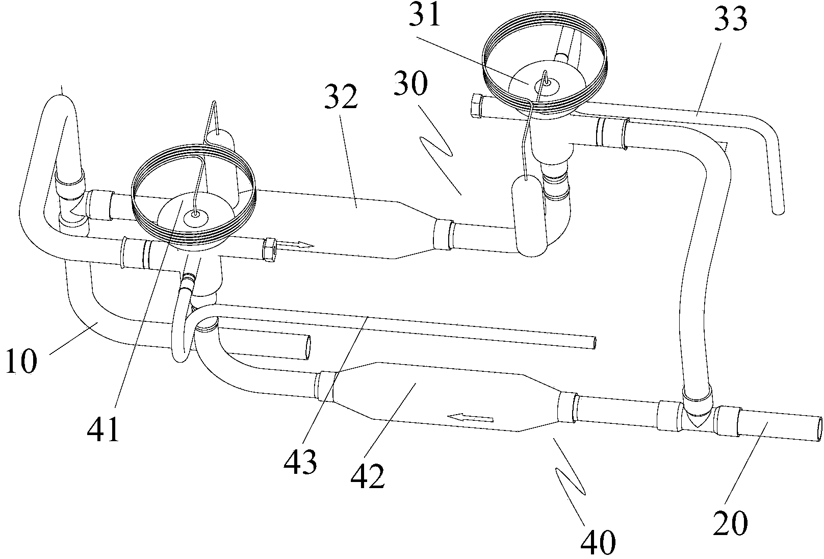
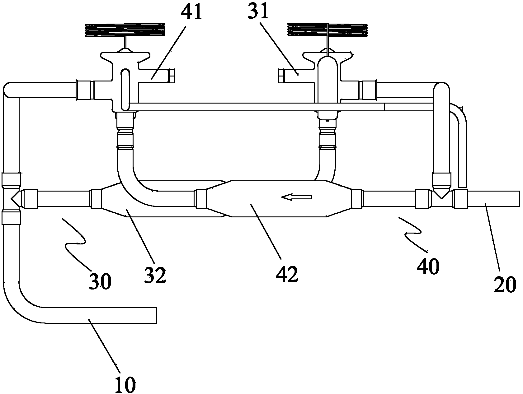
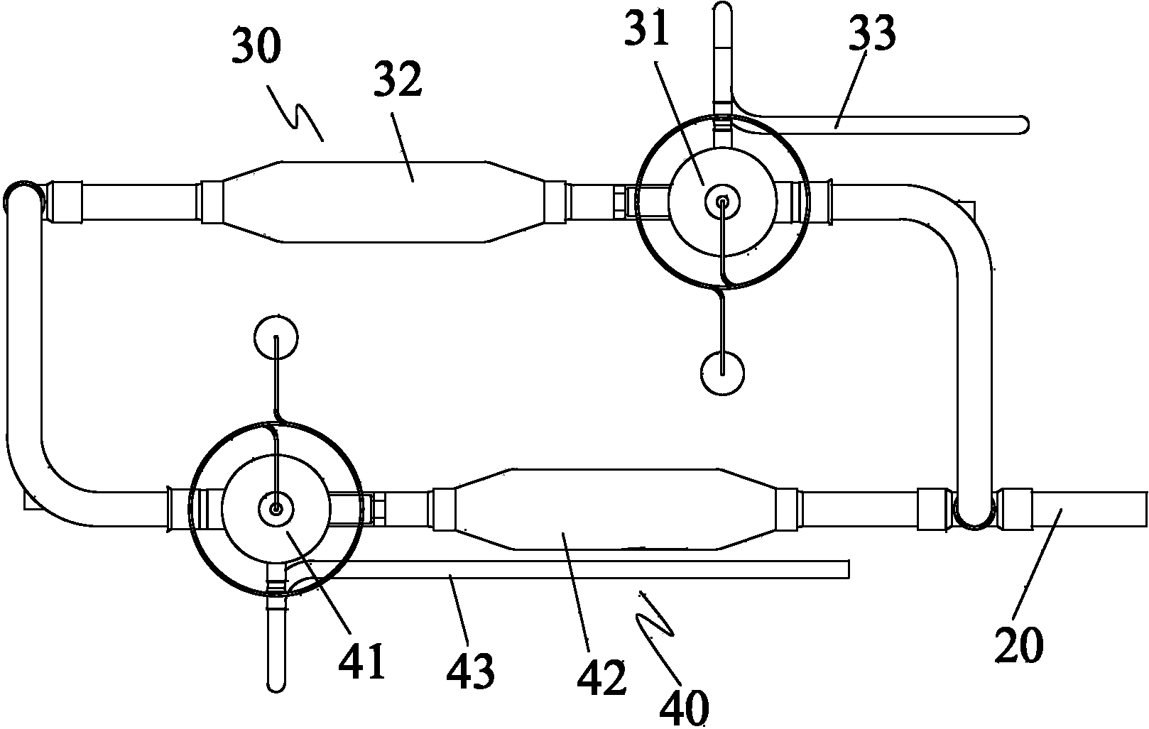
[0017] The direction of the arrow in the figure indicates the flow direction of the refrigerant.

[0018] Such as Figure 1 to Figure 3 As shown, according to the embodiment of the present invention, the throttling structure of the expansion valve includes a first manifold 10 , a second manifold 20 , a first expansion pipeline 30 and a second expansion pipeline 40 . Both the first header pipe 10 and the second header pipe 20 are used to connect with other structures of the heat pump system, so as to apply the throttling structure of the expansion valve of the embodiment of the present invention in the heat pump system.

[0019] The first expansion pipeline 30 is connected between the first main pipe 10 and the second main pipe 20 , and includes a first thermal expansion valve 31 and a...


PUM


Abstract

The invention discloses an expansion valve throttling structure and a heat pump system containing the same. The expansion valve throttling structure comprises a first main pipe (10) and a second main pipe (20), a first expansion pipeline (30) and a second expansion pipeline (40), the first expansion pipeline (30) comprises a first heating power expansion valve (31) and a first control valve (32), the first heating power expansion valve (31) and the first control valve (32) are connected in series, the second expansion pipeline (40) comprises a second heating power expansion valve (41) and a second control valve (42), and the second heating power expansion valve (41) and the second control valve (42) are connected in series. The first expansion pipeline (30) and the second expansion pipeline (40) are arranged in parallel; in a refrigeration state, the first expansion pipeline (30) is connected, and the second expansion pipeline (40) is disconnected; in a heating state, the first expansion pipeline (30) is disconnected, and the second expansion pipeline (40) is connected. The expansion valve throttling structure is simple, convenient to machine, stable, reliable and capable of adjusting the throttling function flexibly.

Description

technical field [0001] The invention relates to the field of heat pump systems, in particular to an expansion valve throttling structure and a heat pump system including the expansion valve throttling structure. Background technique [0002] The compressor, condenser, expansion valve, and evaporator make up the heat pump system. The expansion valve is an important part in the heat pump system, generally installed between the condenser and the evaporator. The expansion valve can make the gas evaporated by the evaporator pressurized and liquefied into a high-temperature and high-pressure liquid refrigerant through the compressor, and throttling through its orifice to become a low-temperature and low-pressure mist liquid refrigerant, and then the refrigerant absorbs in the evaporator The heat achieves the cooling effect. The expansion valve controls the flow rate of the valve through the change of superheat at the end of the evaporator, so as to prevent the liquid impact caus...

Claims


Application Information

Patent Timeline
IPC IPC(8): F25B41/06F25B41/31
Inventor 曾庆新王严杰周江峰罗捷
Owner GREE ELECTRIC APPLIANCES TECH CO LTD OF ZHUHAI
Learn More