3D imaging system and method of industrial CT

An imaging system, 3D technology, applied in the direction of using radiation for material analysis, etc., to achieve the effect of a wide range of applications, simple CT structure, and simple structure

Inactive Publication Date: 2014-11-26
于双悦 +1
View PDF7 Cites 2 Cited by
  • Summary
  • Abstract
  • Description
  • Claims
  • Application Information

AI Technical Summary

Problems solved by technology

[0003] Aiming at the existing 3D imaging method and imaging system of industrial CT, the present invention provides a 3D imaging system of industrial CT and a 3D realization method of industrial CT that collect longitudinal images of objects through scanning

Method used


Image

  • 3D imaging system and method of industrial CT
  • 3D imaging system and method of industrial CT
  • 3D imaging system and method of industrial CT

Examples


Embodiment Construction

[0029] The present invention will be described in further detail below in conjunction with the accompanying drawings.

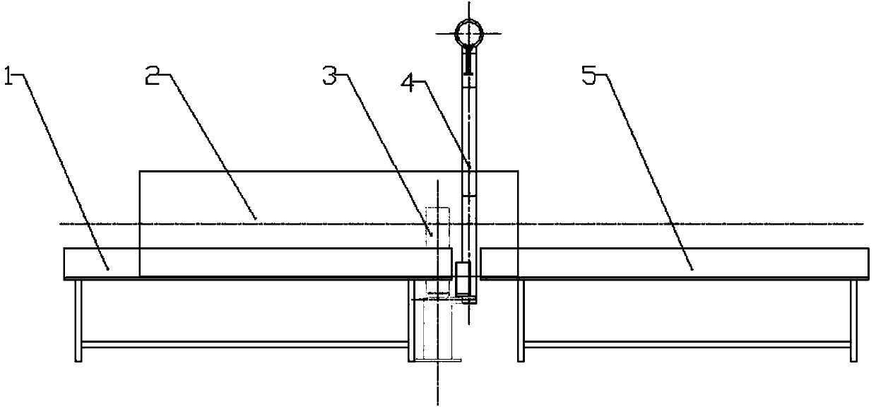
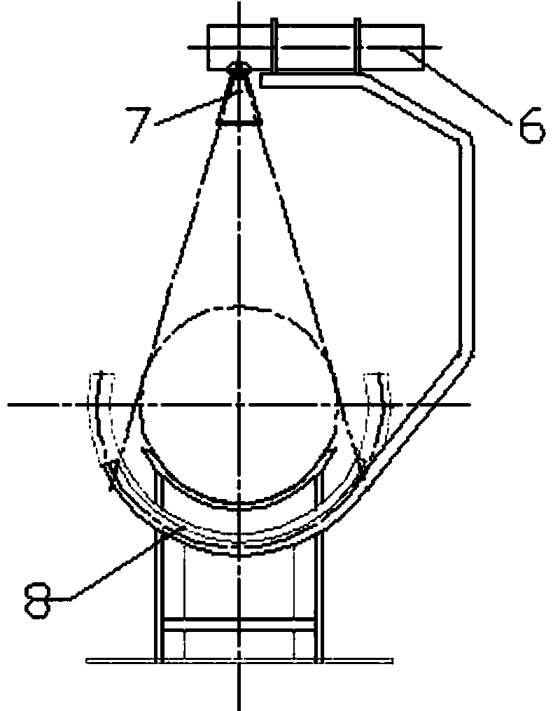
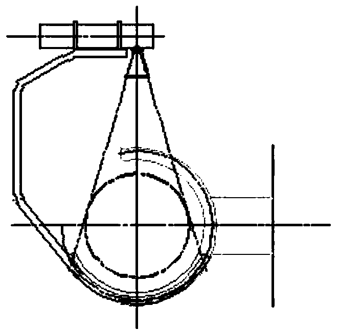
[0030] Such as figure 1 and figure 2 as shown, figure 1 It is a schematic diagram of the main view structure of the 3D imaging system of the industrial CT of the present invention, figure 2 It is a schematic diagram of the side view structure of the 3D imaging system of the industrial CT of the present invention.

[0031] A 3D imaging system for industrial CT, comprising oppositely arranged X-ray generators, arc detectors 8, a primary conveyor belt 5 and a secondary conveyor belt 1 arranged on the same axis, the primary conveyor belt 5 and the There is a gap between opposite ends of the secondary conveyor belt 1 , and the X-ray generator and the arc detector 8 are arranged to rotate around the primary conveyor belt 5 and the secondary conveyor belt 1 with the gap as the center.

[0032] Preferably, the X-ray generator includes an X-ray tube 6 and a beam...


PUM


Abstract

The invention provides a 3D imaging system and method of an industrial CT. The imaging system comprises an X-ray generator, an arc-shaped detector, a primary conveyer belt and a secondary conveyer belt, wherein the X-ray generator and the arc-shaped detector are opposite to each other; the primary conveyer belt and the secondary conveyer belt are arranged on the same axis; a gap is formed between the opposite ends of the primary conveyer belt and the secondary conveyer belt; the X-ray generator and the arc-shaped detector are arranged in a manner of rotating around the primary conveyer belt and the secondary conveyer belt by taking the gas as the circle center. Through longitudinal section type scanning of the 3D imaging system, relatively long objects such as long-columnar objects of dozens of centimeters to dozens of meters as well as internal materials, meters and elements such as water suction pumps, water conservancy generators, aviation undercarriages, aviation engines, diving gears, underwater searching and rescuing devices, bridge components, aerospace vehicles and underwater moving devices can be relatively easily checked by using the 3D imaging method.

Description

technical field [0001] The invention relates to the field of CT imaging, in particular to a 3D imaging system of industrial CT and a 3D realization method of industrial CT. Background technique [0002] At present, industrial non-destructive three-dimensional 3D detection mostly adopts the form similar to medical CT. The item is placed on the conveying device, and the linear array detector and the tube rotate up and down the item at a certain angle (such as 2 degrees) to take a two-dimensional X-ray film and rotate it for a circle. Afterwards, carry out data reconstruction processing on the 180 two-dimensional X-ray films taken, and obtain a slice image of the object with a certain thickness (such as 1 mm), move the object forward for a certain distance (such as 2 mm), and then perform the above-mentioned rotating filming, Obtain the X-ray slice image at this position, and continuously move the item forward to take pictures to obtain a series of slice images of a certain len...

Claims


Application Information

Patent Timeline
Patent Type & Authority Applications(China)
IPC IPC(8): G01N23/04
Inventor 于双悦于红林
Owner 于双悦
Why Eureka
Try Eureka