
Microwave power distributor, microwave power synthesizer and microwave power distribution synthesizer

A microwave power and distributor technology, applied in waveguide-type devices, electrical components, connecting devices, etc., can solve the problems of difficult to guarantee port isolation, bulky, limited power capacity, etc.

Active Publication Date: 2014-11-26
NORTHWEST INST OF NUCLEAR TECH
View PDF7 Cites 11 Cited by
  • Summary
  • Abstract
  • Description
  • Claims
  • Application Information

AI Technical Summary

Problems solved by technology

[0004] Among the microwave synthesizers with high power capacity published internationally in recent years, there are typically synthesizers that couple two orthogonally polarized TE11 modes into the same waveguide, and couple two TE11 modes that are relatively close to the frequency through an overmodulated rectangular waveguide. High-power beat-wave synthesizers, and synthesizers based on overmodulated circular waveguide filter structures, but the above-mentioned synthesizers all have common shortcomings, that is, they are bulky and have limited power capacity, and the isolation between different ports is difficult to guarantee , and the reflection coefficient is high, causing many adverse effects on microwave synthesis

Method used

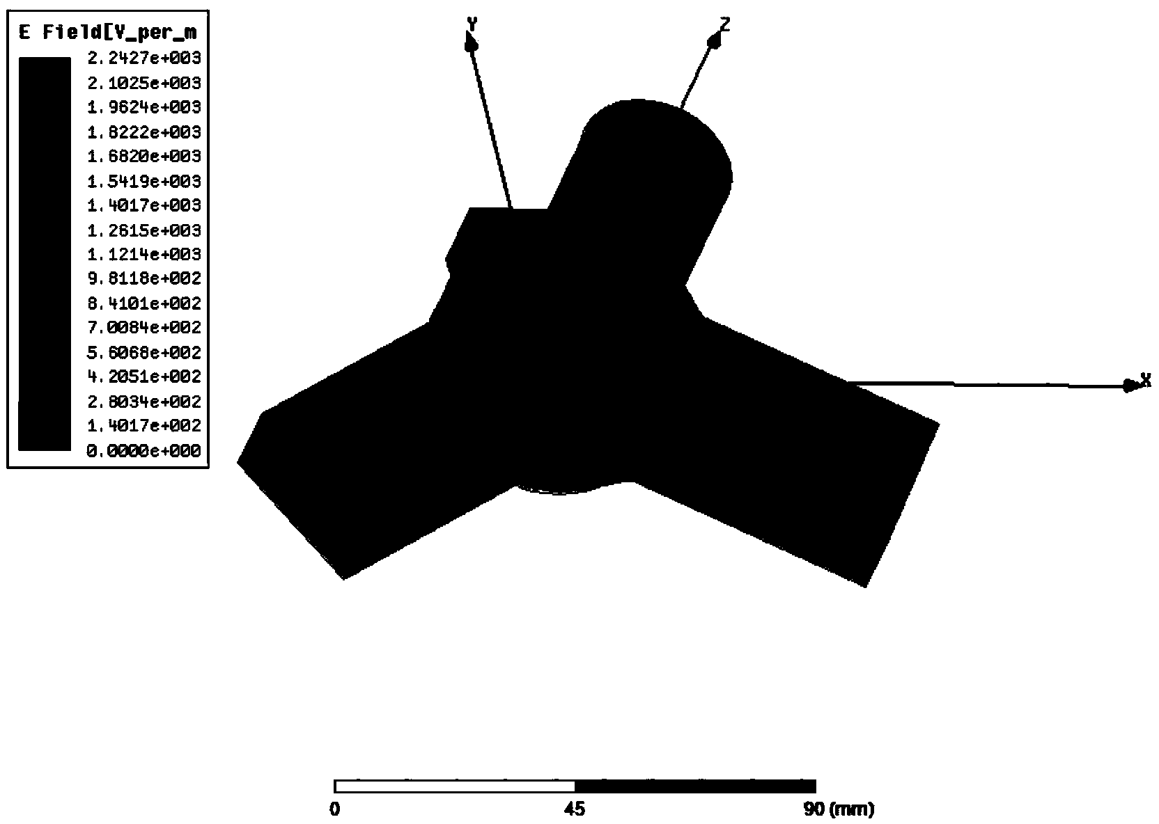
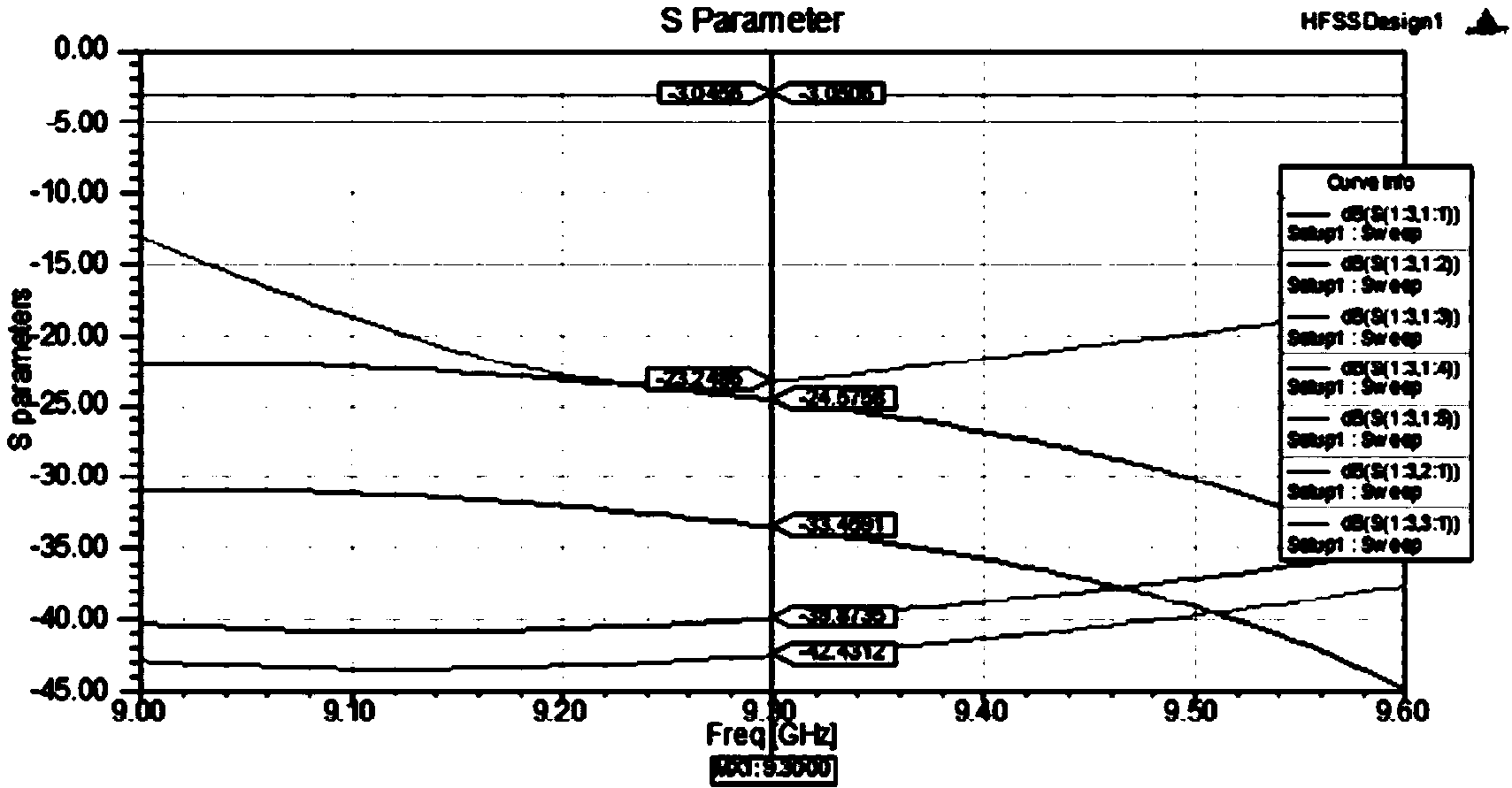

Image

  • Microwave power distributor, microwave power synthesizer and microwave power distribution synthesizer
  • Microwave power distributor, microwave power synthesizer and microwave power distribution synthesizer
  • Microwave power distributor, microwave power synthesizer and microwave power distribution synthesizer

Examples


Embodiment Construction

[0029] In order to more clearly understand the above objects, features and advantages of the present invention, the present invention will be further described in detail below in conjunction with the accompanying drawings and specific embodiments. It should be noted that, in the case of no conflict, the embodiments of the present application and the features in the embodiments can be combined with each other.

[0030] In the following description, many specific details are set forth in order to fully understand the present invention. However, the present invention can also be implemented in other ways different from those described here. Therefore, the protection scope of the present invention is not limited by the specific details disclosed below. EXAMPLE LIMITATIONS.

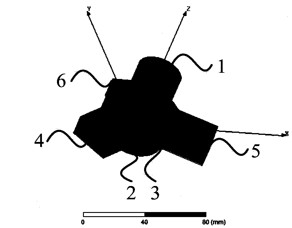
[0031] figure 1 A schematic structural diagram of a microwave power splitter according to an embodiment of the present invention is shown.

[0032] Such as figure 1 As shown, the microwave power divider acc...


PUM


Abstract

The invention relates to a microwave power distributor, a microwave power synthesizer and a microwave power distribution synthesizer. The microwave power distributor comprises a first circular waveguide, a second circular waveguide and a third circular waveguide, wherein the first circular waveguide is used for receiving microwaves and transmitting the microwaves to the third circular waveguide; the second circular waveguide is connected with the third circular waveguide and maintains a short-circuit condition; the third circular waveguide is connected with a first rectangular waveguide, a second rectangular waveguide and a third rectangular waveguide, converts received microwaves into two bundles of microwaves with equal power and identical phase position and transmits the two bundles of microwaves to the first rectangular waveguide and the second rectangular waveguide respectively; the first circular waveguide, the second circular waveguide and the third circular waveguide are TM01-mode circular waveguides and are coaxial; the first rectangular waveguide, the second rectangular waveguide and the third rectangular waveguide are TE10-mode rectangular waveguides, the included angles between the first rectangula waveguide, the second rectangula waveguide and the third rectangula waveguide are all 120 degrees, and the third rectangular waveguide maintains a short-circuit condition. Through the technical scheme, the power capacity of the waveguides in the microwave synthesis process can be improved, a high isolation degree is ensured, the reflection coefficient is lowered, and the microwave synthesis effect is improved.

Description

technical field [0001] The invention relates to the technical field of microwave processing, in particular to a microwave power divider, a microwave power combiner and a microwave power divider combiner. Background technique [0002] High-power microwave (HPM) generally refers to electromagnetic radiation with a frequency between 300MHz and 300GHz and a pulse power exceeding 100MW or an average power of 1MW. The HPM system is the coherent electromagnetic radiation generation, transmission and emission system. The main applications include: (1) Heating controlled thermonuclear plasma through the mechanism of electron cyclotron resonance; (2) Used in high-power short-pulse radar to achieve accurate resolution of detected and tracked targets in a wide frequency band; (3) For Energy transmission between the earth and space; providing energy for the launch of spacecraft into space orbits or transitions between orbits; (4) for high-energy particle radio frequency accelerators for...

Claims


Application Information

Patent Timeline
Patent Type & Authority Applications(China)
IPC IPC(8): H01P5/16
Inventor 常超郭乐田孙钧肖仁珍武晓龙
Owner NORTHWEST INST OF NUCLEAR TECH
Learn More