Power supply apparatus

A technology of power supply device and power supply coil, which is applied in the direction of circuit devices, battery circuit devices, charging stations, etc., which can solve problems such as high temperature and heating, and achieve the effect of inhibiting foreign objects from being heated

Active Publication Date: 2014-11-26
PANASONIC INTELLECTUAL PROPERTY MANAGEMENT CO LTD
View PDF6 Cites 5 Cited by
  • Summary
  • Abstract
  • Description
  • Claims
  • Application Information

AI Technical Summary

Problems solved by technology

There is a problem that foreign matter on the upper surface is heated to a high temperature due to passing through many magnetic fluxes during power supply

Method used


Image

  • Power supply apparatus
  • Power supply apparatus
  • Power supply apparatus

Examples


Embodiment approach 1

[0041]

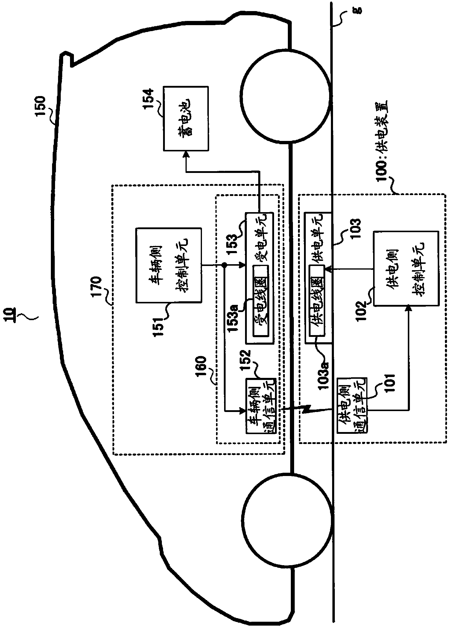
[0042] figure 1 It is a block diagram showing an example of the configuration of charging system 10 in Embodiment 1 of the present invention.

[0043] The charging system 10 has a power supply device 100 , a vehicle 150 , a storage battery 154 , and a charging device 170 .

[0044] The power supply device 100 is installed or buried on the ground so that the power supply unit 103 is exposed from the ground surface g. The power supply device 100 is installed, for example, in a parking space, and is opposed to the power receiving unit 153 to supply power to the charging device 170 while the vehicle 150 is parked. In addition, the configuration of the power supply device 100 will be described later.

[0045] Vehicle 150 has battery 154 and charging device 170 , and runs with battery 154 as a power source. The vehicle 150 is, for example, HEV (Hybrid Electric Vehicle, gasoline-electric hybrid vehicle), PHEV (Plug-in Hybrid Electric Vehicle, plug-in hybrid electric veh...


PUM


Abstract

A power supply apparatus capable of inhibiting temperature increase of a foreign substance heated during power supply while suppressing the thickness of a cabinet surface. In the power supply apparatus (100), on a top surface (202a), which is the surface opposing the power-receiving unit (153) of a cabinet (103b), in the portion where a power supply coil (103a) is projected when the power supply coil (103a) is projected on the cabinet (103b) toward the direction of the power-receiving unit (153), a first inclined part (203) gradually approaching the power supply coil (103a) from the top section (205) toward the inner edge section (211) of the power supply coil (103a) is formed in the radial direction of the power supply coil (103a), and in the portion where the power supply coil (103a) is projected, a second inclined part (204) gradually approaching the power supply coil (103a); from the top section (205) toward the outer periphery (212) of the power supply coil (103a) is formed in the radial direction of the power supply coil (103a).

Description

technical field [0001] The present invention relates to a power supply device that uses electromagnetic induction to supply power to a power receiving unit provided in a vehicle in a non-contact manner. Background technique [0002] Conventionally, as a non-contact power feeding device, a device installed on the ground to feed power to a power receiving unit mounted on a vehicle is known (for example, Patent Document 1). [0003] In Patent Document 1, two units are included: a power transmitting unit and a power receiving unit. The power transmission unit has an annular power transmission coil and a case for accommodating the coil, and is installed on the road surface side of a parking space where the vehicle stops. The power receiving unit has an annular power receiving coil and a case for accommodating the coil, and is installed on the bottom surface of the vehicle at a position opposite to the power transmitting unit installed on the ground. The case surface (hereinafte...

Claims


Application Information

Patent Timeline
Patent Type & Authority Applications(China)
IPC IPC(8): H02J17/00H02J7/00
CPCY02T90/14Y02T10/7072H02J50/80H02J7/00034B60L53/126B60L53/124H02J2310/48Y02T10/70H02J50/12H02J50/60Y02T90/12H02J50/10
Inventor 龙田利树大桥修西尾刚朝冈则明小泉正刚
Owner PANASONIC INTELLECTUAL PROPERTY MANAGEMENT CO LTD
Why Eureka
Try Eureka