
Sheet Holder

A technology for holding devices and thin plates, which is used in auxiliary devices, laser welding equipment, auxiliary welding equipment, etc., to achieve the effect of simple operation

Active Publication Date: 2017-10-03
SUMITOMO HEAVY IND LTD
View PDF9 Cites 0 Cited by
  • Summary
  • Abstract
  • Description
  • Claims
  • Application Information

AI Technical Summary

Problems solved by technology

[0004] However, there is a problem that it is difficult to hold the thin plate on the XY table while applying a tension that overcomes the injection pressure of the assist gas to the thin plate, requiring proficiency.

Method used


Image

  • Sheet Holder
  • Sheet Holder
  • Sheet Holder

Examples


Embodiment Construction

[0036] The best mode for carrying out the present invention will be described below with reference to the drawings. figure 1 It is a front view of the laser processing machine 1 according to the first embodiment of the present invention. Such as figure 1 As shown, the laser processing machine 1 is mainly composed of: a processing head 4 for irradiating a laser beam to a thin plate W to be processed and injecting assist gas; A processing head 4 for irradiating laser light is suspended from the arm 2 via a horizontal moving member 3 . The horizontal moving member 3 is configured to be movable in the Y direction with respect to the arm 2 by the Y-axis driving device 3a, while the machining head 4 is configured to be movable in the X direction with respect to the horizontal moving member 3 by the X-axis driving device 4a. The machining head 4 is driven by the X-axis driving device 3 a and the Y-axis driving device 4 a to move in the XY direction with respect to the arm 2 .

[0...


PUM


Abstract

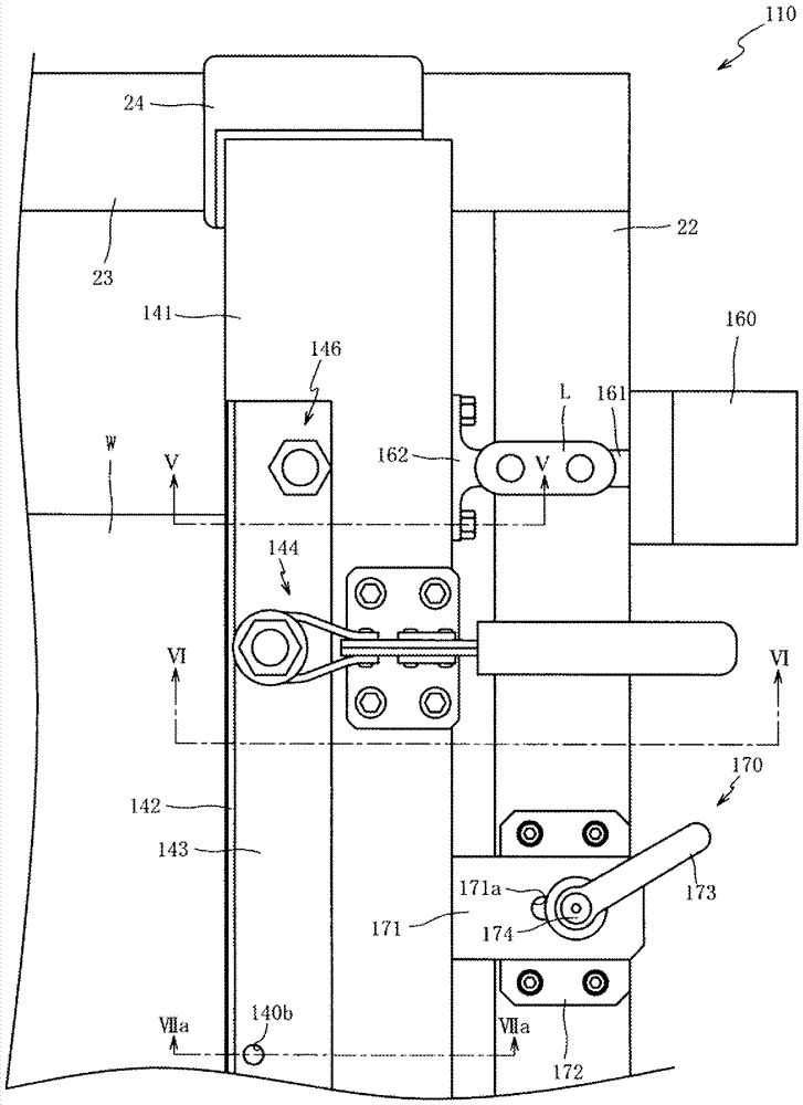
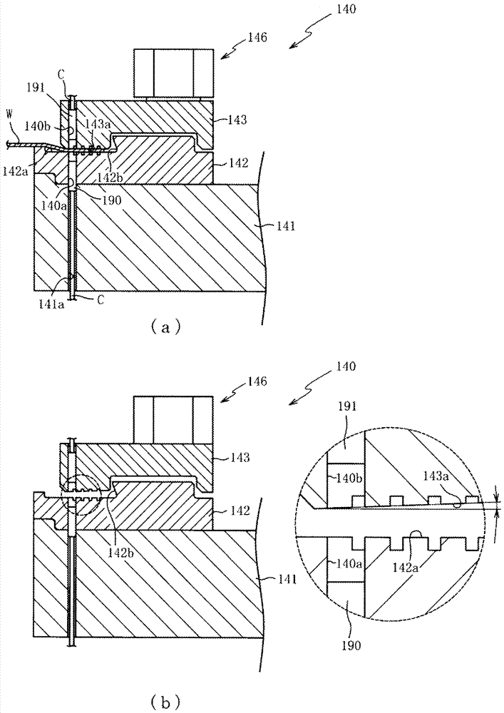
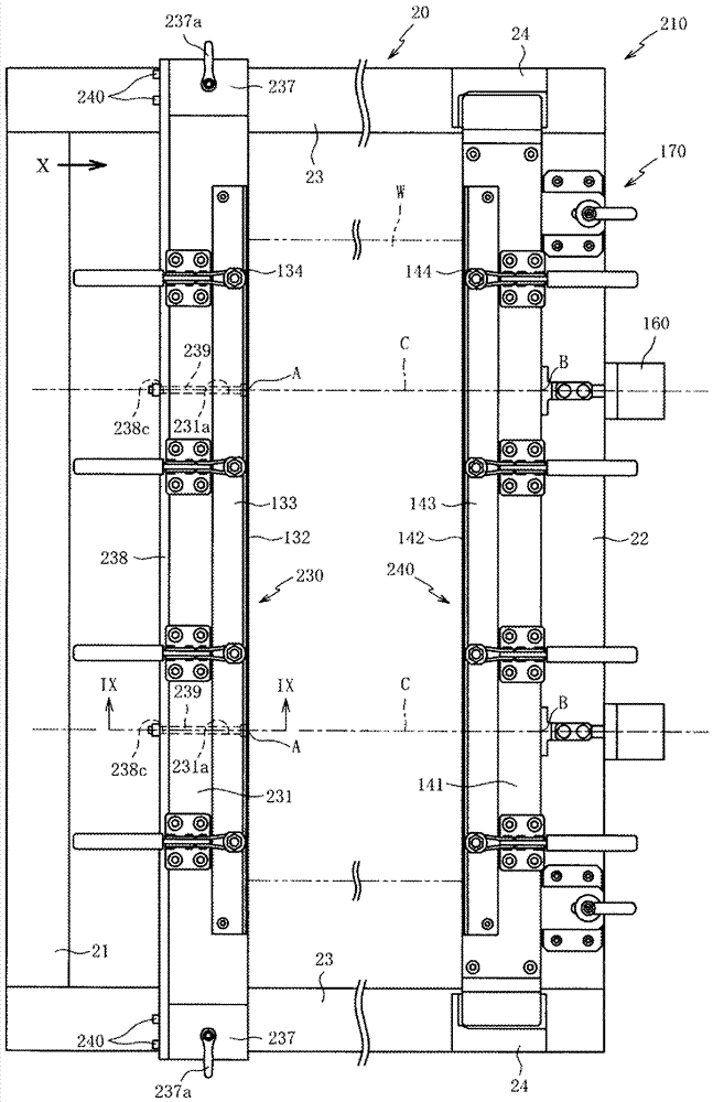
The invention provides a thin plate retaining device capable of arranging a thin plate on an XY platform in an opening mode by simple and convenient operation in a laser machine. A first frame material (21) and a second frame material (22) are fixedly arranged on the XY platform (11), and are spaced from each other by a given distance. A first part (130) is arranged between the first frame material (21) and the second frame material (22), and one end of a thin plate (W) is clamped by the first part (130). A second part (140) is formed by relatively moving from a direction away from the first part (130), and is arranged between the first frame material (21) and the second frame material (22) along the second frame material (22), and the other end of the thin plate (W) is clamped by the second part (22). The ends of multiple connecting rods (L) which are formed in a swinging way are connected with the corresponding multiple parts of the second part (22), and the other ends of the connecting rods (L) are connected with a cylinder (160). The thin plate (W) can be arranged on the XY platform (11) by the simple and convenient operation that force is applied to the second frame material (22) by the second part (140).

Description

technical field [0001] The present invention relates to a thin plate holding device in a laser processing machine for processing a thin plate to be processed by irradiating laser light. Background technique [0002] A laser processing machine is used for microfabrication of a workpiece formed of a thin metal plate. In a laser processing machine, a thin plate is stretched on an XY stage that moves in a plane in a direction perpendicular to the optical axis of a laser, the thin plate is moved in the XY direction by the XY stage, and the thin plate is cut by irradiating focused laser light from a processing head. When cutting a thin plate with high precision and high quality, the focal point of the laser light on the thin plate is made as small as possible so that the focus position does not change, and assist gas is injected to the thin plate (processed part). By spraying the assist gas to the thin plate, it is possible to blow off molten matter scattered from the cut portion...

Claims


Application Information

Patent Timeline
Patent Type & Authority Patents(China)
IPC IPC(8): B23K26/70B23K26/38B23K37/04
CPCB23K26/38B23K37/0408
Inventor 藤泽佳生古田泰之
Owner SUMITOMO HEAVY IND LTD
Learn More