Double-track trolley group running mechanism for ultra-large gantry crane

A super-large door and operating mechanism technology, applied in the directions of walking mechanism, rail system, transportation and packaging, etc., can solve the problems of high manufacturing cost, weakened horizontal rigidity, complex stress, etc., to facilitate maintenance and maintenance, and reduce construction costs. , the effect of increasing the working range

Active Publication Date: 2014-12-03
ZHONGCHUAN NO 9 DESIGN & RES INST
View PDF6 Cites 7 Cited by
  • Summary
  • Abstract
  • Description
  • Claims
  • Application Information

AI Technical Summary

Problems solved by technology

At the same time, the hinge shaft of the balance beam is directly installed on the steel sleeve on the transmission shaft, so that the transmission shaft bears the action of torque and bending moment at the same time, and the force is complicated. Therefore, the bearing capacity of the transmission shaft and the left and right wheel gauges are limited.
Once the gauge is limited, the effect of overcoming rail gnawing is weakened, and the advantages of the double-track trolley cannot be fully displayed.
[0006] The problems existing in the prior art are: the trolley trolley of the ultra-large gantry crane needs to withstand relatively large wheel pressure, and the wheels are made of large-diameter cast or forged alloy steel materials, and the manufacturing cost is high, especially the huge running wheel. The quantity not only increases the work blind spot but also weakens the horizontal rigidity, which not only increases the basic investment, aggravates the phenomenon of rail gnawing, but also causes waste

Method used


Image

  • Double-track trolley group running mechanism for ultra-large gantry crane
  • Double-track trolley group running mechanism for ultra-large gantry crane
  • Double-track trolley group running mechanism for ultra-large gantry crane

Examples


Embodiment Construction

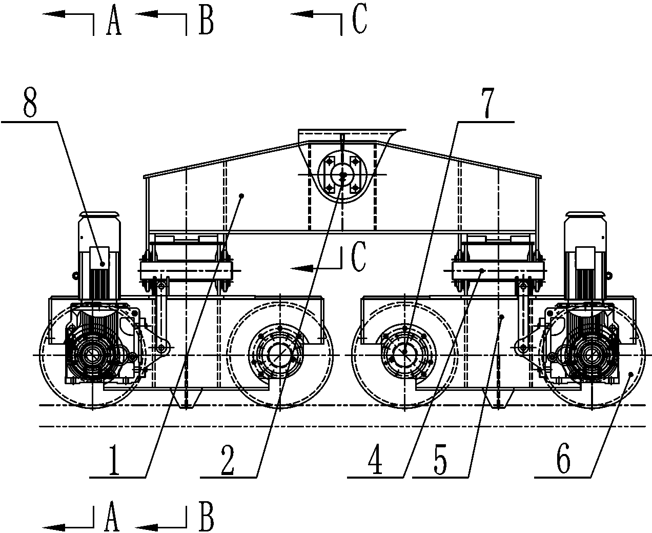
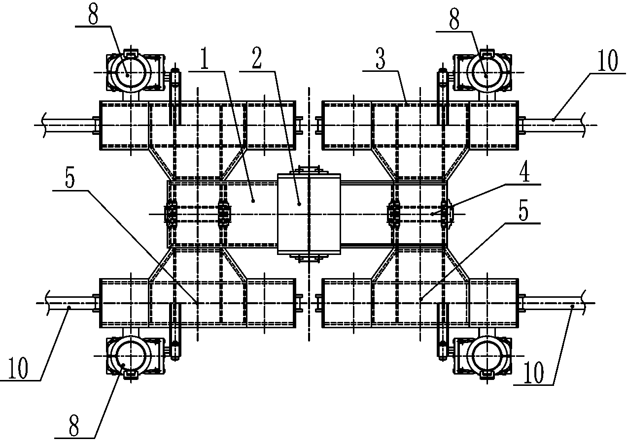
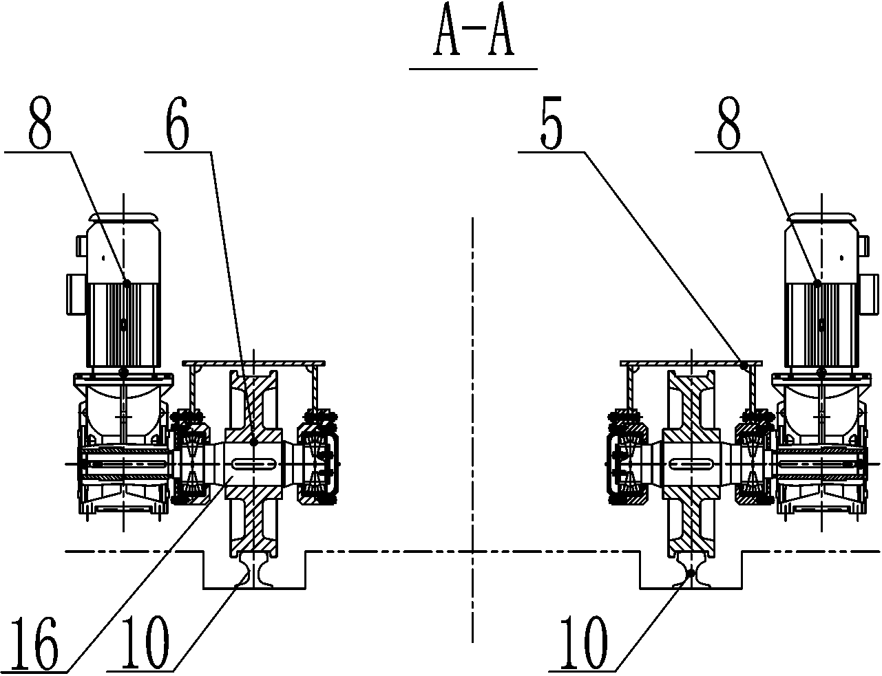
[0020] See attached figure 1 ~ attached figure 2 , the present invention is made up of balance beam 1 and double-track trolley 3, and described double-track trolley 3 is a four-wheel dual-drive mechanism composed of running wheels 6 and driven wheels 7 symmetrically arranged on both sides of vehicle frame 5. The double-track trolley 3 is fixedly arranged at both ends of the balance beam 1 by the hinge shaft 4, and the double-track trolley 3 and the balance beam 1 are hingedly connected. The vehicle frame 5 is an "I"-shaped box structure. The driven wheel 7 is fixedly arranged on the vehicle frame 5 by a wheel shaft. Described traveling wheel 6 is the driving wheel that is provided with driving mechanism 8, and driving mechanism 8 makes traveling wheel 6 promote driven wheel 7 and drives the trolley group that is made up of two double-track trolleys 3 to run on track 10 together. The driving mechanism 8 is a three-in-one device of a motor, a reducer and a brake. The driven...


PUM


Abstract

The invention discloses a double-track trolley group running mechanism for an ultra-large gantry crane. The double-track trolley group running mechanism comprises an equalizing beam and double-track trolleys. The double-track trolley group running mechanism is characterized in that each double-track trolley is a four-wheel double-drive mechanism which is formed by travelling wheels and driven wheels which are symmetrically arranged on two sides of a trolley frame; the double-track trolleys are fixedly arranged at the two ends of the equalizing beam through hinged shafts, and the double-track trolleys are in hinged connection with the equalizing beam; the trolley frame is of an I-shaped box structure; the travelling wheels are driving wheels provided with driving mechanisms, and the driving mechanisms can enable the traveling wheels and the driven wheels to drive a trolley group composed of the two double-track trolleys to run on tracks. Compared with the prior art, the double-track trolley group running mechanism has the advantages of low wheel pressure of the traveling wheels, uniform distribution of wheel pressure, and is capable of greatly weakening lateral force, effectively avoiding the rail gnawing phenomenon, enlarging the working range, reducing the working blind area and further reducing project construction cost. The double-track trolley group running mechanism is simple in structure and greatly convenient to maintain.

Description

[0001] technical field [0002] The invention relates to the technical field of hoisting equipment, in particular to an operating mechanism of a double-track trolley group of an ultra-large gantry crane. Background technique [0003] At present, the trolleys of the trolley operating mechanism of super-large gantry cranes are mostly monorail trolleys. The monorail trolley consists of two wheels, a trolley frame, a wheel shaft, a small balance beam hinged with the trolley frame, and a drive devices etc. The ultra-large gantry crane has only two cart rails, which are respectively located under the rigid outriggers and flexible outriggers or fully rigid legs on both sides. The monorail trolley of the traveling mechanism under the outrigger on one side runs on one rail. Each monorail trolley is supported by two wheels to support the self-weight and hoisting weight of the crane, and can walk along the cart track driven by the reducer, and the trolley is connected by a balance bea...

Claims


Application Information

Patent Timeline
Patent Type & Authority Applications(China)
IPC IPC(8): B66C9/00B66C9/14B66C7/00
Inventor 严旭东钮信宝俞力生马骏徐兆君李锋
Owner ZHONGCHUAN NO 9 DESIGN & RES INST
Why Eureka
Try Eureka