
Instant cloth cover quality detection system

A detection system and quality technology, applied in textiles, textiles, papermaking, looms, etc., can solve problems such as weft yarn slipping and affecting the smoothness of the coating surface

Active Publication Date: 2014-12-03
重庆亿煊新材料科技有限公司
View PDF9 Cites 4 Cited by
  • Summary
  • Abstract
  • Description
  • Claims
  • Application Information

AI Technical Summary

Problems solved by technology

[0004] In view of this, this application provides a real-time detection system for the quality of the cloth surface to overcome the defects in the prior art that are caused by high-speed weft insertion during weaving and weaving into the cloth surface. Surface flatness and other quality accidents

Method used


Image

  • Instant cloth cover quality detection system
  • Instant cloth cover quality detection system

Examples


Embodiment 1

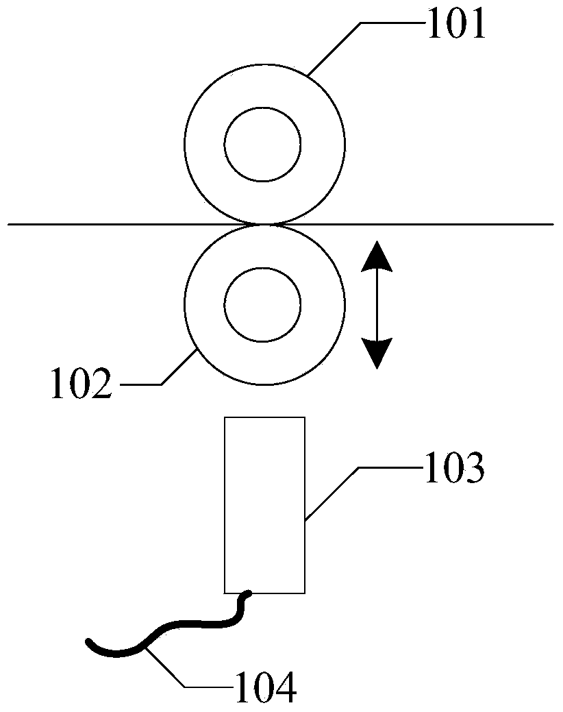
[0029] Embodiment 1 of the present application provides a real-time detection system for cloth surface quality, such as figure 1 as shown, figure 1 It is a schematic structural diagram of a real-time cloth quality detection system provided in Embodiment 1 of the present application. The detection system includes: a first bearing 101 , a second bearing 102 , a proximity switch 103 and a proximity switch wire 104 .

[0030] The rolling surfaces of the first bearing 101 and the second bearing 102 are contactable, and are used for guiding the weft yarn and fixing the longitudinal position of the weft yarn.

[0031] Wherein, the first bearing 101 is a fixed rotating bearing, and the second bearing 102 is a bearing that can slide perpendicular to the traveling direction of the weft yarn.

[0032] When the second bearing 102 slides away from the first bearing 101, it contacts with the sensing end of the proximity switch 103 to trigger the proximity switch 103. After the proximity s...

Embodiment 2

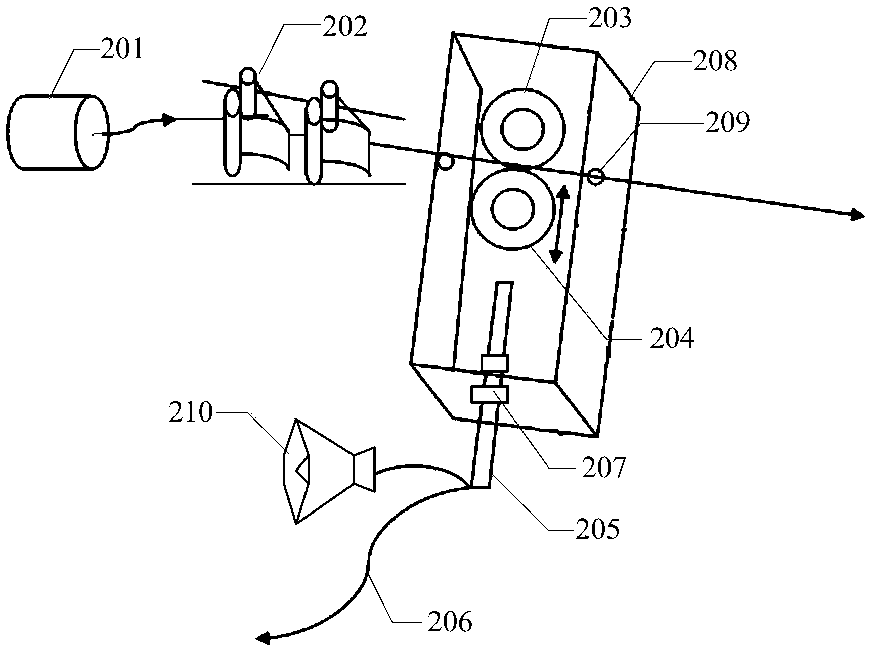
[0036] Embodiment 2 of the present application provides another kind of real-time detection system of cloth surface quality, such as figure 2 as shown, figure 2 It is a schematic structural diagram of a real-time cloth quality detection system provided in Embodiment 2 of the present application. The detection system includes: yarn reel 201, weft tensioner 202, first bearing 203, second bearing 204, proximity switch 205, proximity switch wire 206, adjustment nut 207, base 208, magnetic eye 209 and alarm device 210.

[0037] The yarn roll 201 is used for providing weft yarn.

[0038] The weft yarn tensioner 202 is used to apply tension to the weft yarn leading to the shed of the loom, and to eliminate the air loop generated when the weft yarn is unwound from the yarn roll.

[0039] Wherein, the weft yarn tensioner can be composed of a tension sheet and a tension sheet fixing device, and of course it can also be other devices capable of providing a certain tension for the wef...


PUM


Abstract

The invention provides an instant cloth cover quality detection system which comprises a first bearing, a second bearing, a proximity switch and a proximity switch wire. The first rolling can be in contact with the roll face of the second bearing and is used for guiding weft yarns and fixing the longitudinal positions of the weft yarns. The first bearing is a fixed rotating bearing, and the second bearing can slide in the direction perpendicular to the weft yarn advancing direction. When the second bearing slides towards the direction away from the first bearing, the second bearing makes contact with a sensing end of the proximity switch to trigger the proximity switch, and when the proximity switch is triggered, the proximity switch controls a starting / closing switch of a loom to be switched off through the proximity switch wire. By means of the instant cloth cover quality detection system, weft yarn knot detection or weft yarn ring detection can be rapidly and sensitively conducted on the weft yarns about to entering the cloth cover in the weaving process, so that the weft yarn knots or the weft yarn rings can be eliminated or the loom stops working automatically, and thus influences, brought out by defect points generated on the cloth cover, on the coated surface smoothness in the next process are avoided.

Description

technical field [0001] The present application relates to the technical field of weaving, in particular to a real-time detection system for cloth surface quality. Background technique [0002] Fiberglass ripstop is a fabric composed of glass fiber rovings or spun yarns that interweave the warp and weft yarns through the movement of the loom. According to the different ways of warp and weft yarn interweaving, it can be divided into plain weave, twill weave, satin weave and so on. Glass fiber cloth is widely used in various industries such as wind power, automobile industry, electronics industry, construction industry, etc. These fields require good flatness of glass fiber cloth. If the flatness of glass fiber cloth is not good, it will be used in the next process Dipping or coating processes are affected. [0003] However, during weaving, high-speed weft insertion will cause the weft yarn to slip off or the weft yarn to be knotted. Since the loom is running all the time, th...

Claims


Application Information

Patent Timeline
Patent Type & Authority Applications(China)
IPC IPC(8): D03J1/04D03D51/18
Inventor 邓阳
Owner 重庆亿煊新材料科技有限公司
Learn More