[0019] In order to make the objectives, technical solutions, and advantages of the present invention clearer, the following further describes the present invention in detail in conjunction with specific embodiments and with reference to the accompanying drawings. It should be noted that in the drawings or description of the specification, similar or identical parts use the same drawing numbers. The implementations not shown or described in the drawings are those known to those of ordinary skill in the art. In addition, although this article may provide an example of a parameter containing a specific value, it should be understood that the parameter does not need to be exactly equal to the corresponding value, but can be approximated to the corresponding value within acceptable error tolerances or design constraints. The directional terms mentioned in the embodiments, such as "upper", "lower", "front", "rear", "left", "right", etc., are only directions with reference to the drawings. Therefore, the directional terms used are used to illustrate and not to limit the protection scope of the present invention.
[0020] The present invention provides a test system and method for the response characteristics of light-emitting diodes, which can realize simultaneous, rapid, quantitative detection and real-time data recording and processing analysis of light and electrical responses to the response characteristics of light-emitting diodes, with high detection efficiency and accuracy High performance and can realize automated testing.
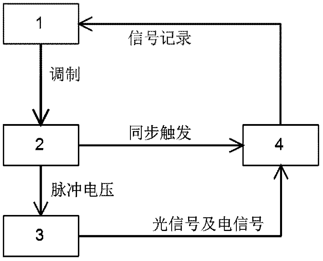
[0021] In an exemplary embodiment of the present invention, a test system for the response characteristics of a light emitting diode is provided. figure 1 It is a schematic structural diagram of a light emitting diode response characteristic test system according to an embodiment of the present invention. Such as figure 1 As shown, the test system for the response characteristics of the light-emitting diode of this embodiment includes: a computer modulation module 1 for sending pulse voltage parameters and analyzing the received light response and electrical response data; a pulse voltage generating module 2 connected to The computer modulation module 1 is used to generate a pulse voltage according to the pulse voltage parameters issued by the computer modulation module 1, and load the pulse voltage to the light emitting diode 3 to be tested; the data acquisition module 4 is used to collect the light emitting diode 3 to be tested And send the light response and electrical response data to the computer modulation module 1. Among them, the light emitting diode 3 is connected to the pulse voltage generating module 2 and emits light under the driving of the pulse voltage generated by the pulse voltage generating module.
[0022] The components of the test system for the response characteristic of the light-emitting diode of this embodiment will be described in detail below.
[0023] In this embodiment, the computer modulation module (1) sets the pulse voltage output command as: the pulse voltage waveform is a rectangular waveform, the pulse intensity is 13.0V, the pulse frequency is 33 Hz, and the pulse width is 16 μs.
[0024] Among them, the computer modulation module 1 is connected to the pulse voltage generation module 2 and the data acquisition module 4 through a USB data transmission line. The computer modulation module 1 has the function of individually or simultaneously adjusting the waveform, frequency, intensity, pulse width and other parameters of the pulse voltage output module 2 output pulse voltage, and can automatically output pulse output instructions with a certain changing law through program settings. In addition, the computer modulation module 1 can realize real-time recording, processing and analysis of the data collected by the data acquisition module 4.
[0025] The pulse voltage generating module 2 is composed of an electric pulse generator capable of generating an adjustable pulse voltage. The intensity, frequency, waveform and pulse width of the pulse voltage generated by the electric pulse generator are modulated by the computer modulation module 1.
[0026] The light emitting diode 3 is connected in series with the pulse voltage generating module 2. The light emitting diode 3 is driven by a pulse voltage; the light emitting diode can be any one of an inorganic electroluminescent diode LED and an organic electroluminescent diode OLED.
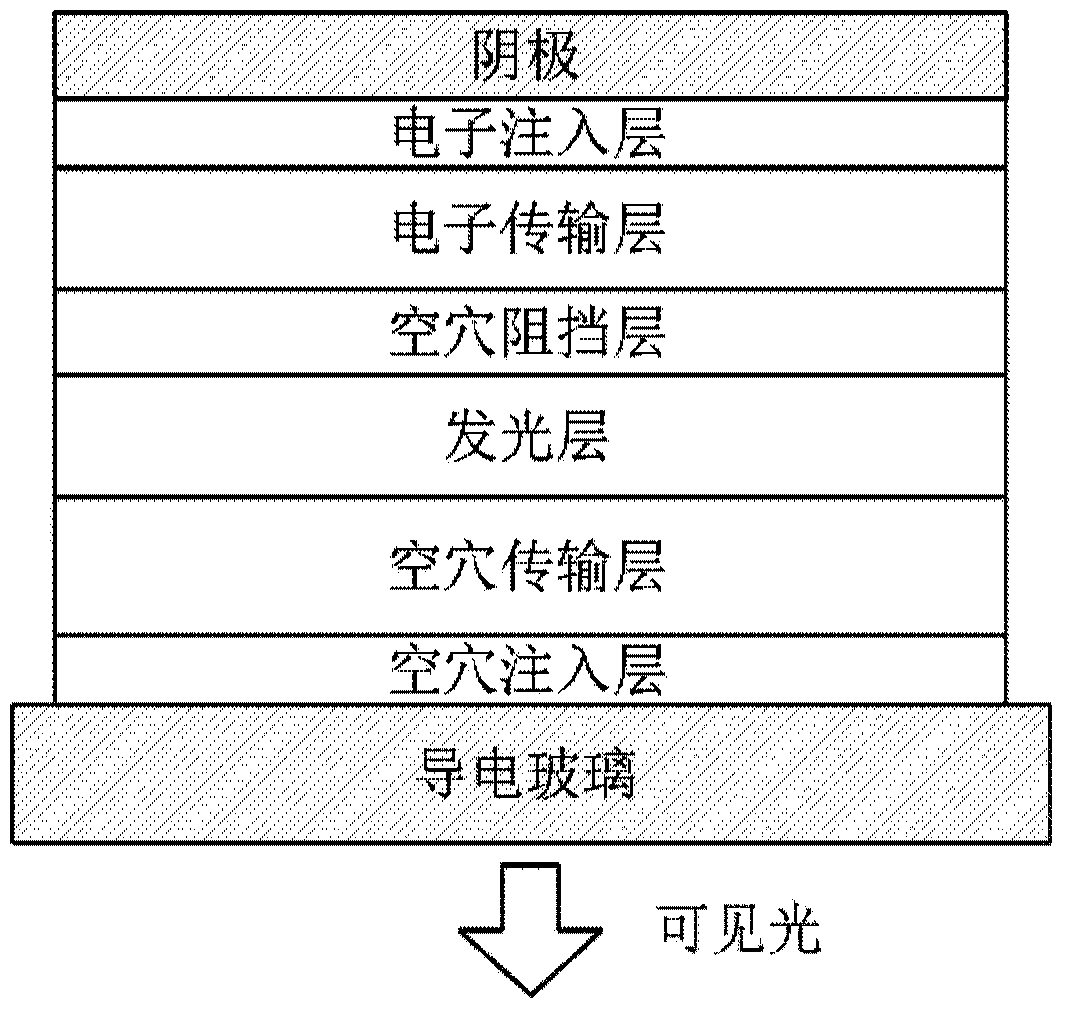
[0027] figure 2 for figure 1 The cross-sectional structure diagram of the organic light-emitting diode in the light-emitting diode response characteristic test system is shown. Such as figure 2 As shown, the light-emitting diode in this embodiment uses an organic electroluminescent diode OLED, and its composition is: ITO/MoO 3 /NPB/Alq 3 /BCP/Alq 3 /LiF/Al, where ITO is conductive glass, MoO 3 It is a hole injection layer, NPB is a hole transport layer, adjacent to Alq of NPB 3 It is a light-emitting layer, BCP is a hole blocking layer, and Alq adjacent to LiF 3 Is the electron transport layer, LiF is the electron injection layer, Al is the cathode, and the emission wavelength is 542nm.
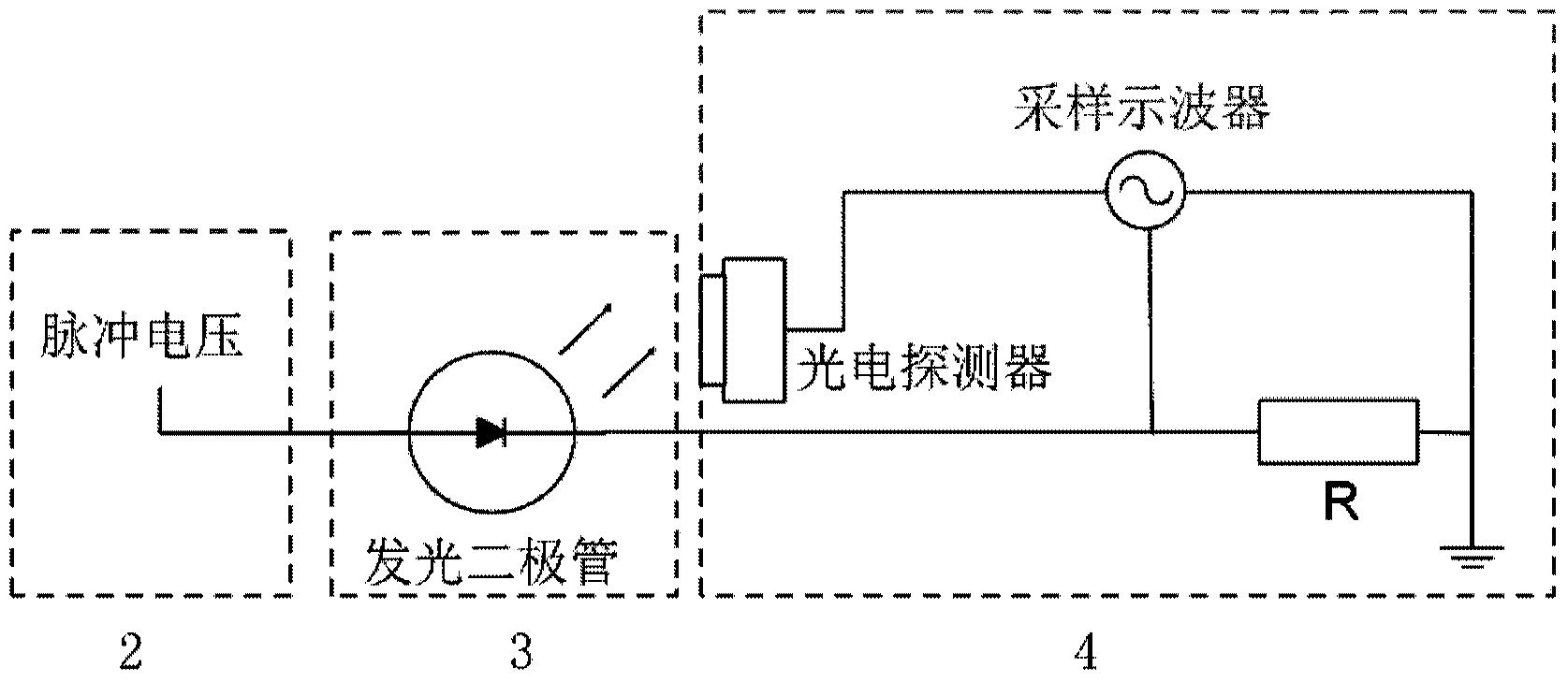
[0028] image 3 for figure 1 The circuit connection diagram of the light-emitting diode and the data acquisition module in the light-emitting diode response characteristic test system is shown. Such as image 3 As shown, the signal acquisition module 4 in this embodiment includes:
[0029] The sampling resistor R is connected in series with the light emitting diode 3, one end of which is electrically connected to the output end of the light emitting diode, and the other end is grounded;
[0030] A photodetector whose response wavelength matches the wavelength of light emitted by the light-emitting diode, and its optical probe faces the light-emitting side of the light-emitting diode;
[0031] Sampling oscilloscope whose clock port is connected with the clock port of pulse voltage generating module 2 to realize synchronous triggering of the signal. Its first input terminal is connected to the signal output terminal of the photodetector, and its second input terminal is connected to the light emitting diode The circuit node between the sampling resistor R and the signal output terminal is connected to the computer modulation module 1 through the USB data transmission line, and is used to sample the output signal of the first input terminal and the second input terminal, and the data generated by the sampling Transfer to the computer modulation module 1.
[0032] In this embodiment, the sampling resistor adopts a fixed value resistor with a resistance value of 50Ω. The photodetector uses a high-sensitivity photomultiplier tube with a response wavelength of 460-600nm. The sampling oscilloscope can be any one of a single-wire oscilloscope plus a switch, a two-wire/multi-wire oscilloscope, and a double-trace/multi-trace oscilloscope, which is connected to the computer modulation module 1 through a USB data transmission line.
[0033] So far, the introduction of the test system for the response characteristics of the light-emitting diode of this embodiment is complete.
[0034] In another embodiment of the present invention, there is also provided a method for testing the response characteristics of light-emitting diodes by using the above-mentioned test system. The method includes the following steps:
[0035] Step A: Press figure 1 The structural schematic diagram shown is to build the test system of the present invention and adjust the light path so that the light emitted by the light emitting diode 3 can be collected by the highly sensitive photodetector in the data collection module 4;
[0036] Step B: Set the output command of the computer modulation module, the waveform is set to a rectangular waveform, the pulse intensity is 13.0V, the pulse frequency is 33Hz, and the pulse width is 16μs;
[0037] Step C: The pulse voltage generation module receives the pulse voltage output instruction and outputs the corresponding pulse voltage. The pulse voltage is loaded on the light-emitting diode and collected and recorded by the sampling oscilloscope as a calibration curve;
[0038] Step D: The light emitting diode is driven to emit light by the pulse voltage;
[0039] Step E: The photomultiplier tube collects the optical signal emitted by the light-emitting diode, converts it into an electrical signal, and inputs it to the sampling oscilloscope; at the same time, the sampling oscilloscope collects the voltage at both ends of the sampling resistor; the sampling oscilloscope responds to the collected optical signal data and electrical response Data is input to the computer modulation module in real time;
[0040] Step F: The computer modulation module records and processes and analyzes the output data of the light response sampling oscilloscope and the electrical response sampling oscilloscope in real time to obtain the light response and electrical response characteristics of the light emitting diode.
[0041] Figure 4 For use figure 1 The light-emitting diode response characteristic test system shows the light-emitting diode light response and electrical response curve obtained by the test. by Figure 4 The middle curve can respectively obtain the response characteristics of the OLED device in this experiment, such as the light response time characteristic, light intensity change law, electrical response time characteristic, and quantitative value of current.
[0042] So far, the test method of the response characteristic of the light-emitting diode of this embodiment has been introduced.
[0043] So far, two embodiments of the present invention have been described in detail with reference to the drawings. Based on the above description, those skilled in the art should have a clear understanding of the test system and test method for the response characteristics of the light-emitting diode of the present invention.
[0044] In addition, the above definitions of various elements and methods are not limited to the various specific structures, shapes or methods mentioned in the embodiments, and those of ordinary skill in the art can simply modify or replace them; for example:
[0045] (1) The sampling resistor adopts a small resistor, and its resistance value can be between 10Ω~100Ω, not limited to 50Ω in the above embodiment;
[0046] (2) The wavelength of the light-emitting diode is between 380nm and 700nm, and the response wavelength of the corresponding photodetector is between 350nm and 750nm, which is not limited to the relevant content in the above embodiment;
[0047] (3) The pulse voltage parameters in the instruction output from the computer modulation module to the pulse voltage generation module, such as pulse intensity and pulse frequency, can be adjusted as needed, and are not limited to the values mentioned in the above embodiments.
[0048] In summary, the test system and test method of the LED response characteristics of the present invention can not only realize the rapid measurement of the light response and electrical response of the LED under pulse voltage, but also can easily realize the light response and electrical response of the LED under different pulse voltage signals. Responsive automatic detection has broad application prospects in the field of photoelectric detection.
[0049] The specific embodiments described above further describe the purpose, technical solutions and beneficial effects of the present invention in further detail. It should be understood that the above descriptions are only specific embodiments of the present invention and are not intended to limit the present invention. Any modification, equivalent replacement, improvement, etc., made within the spirit and principle of the present invention should be included in the protection scope of the present invention.