Large-zoom-ratio zooming laser illuminator

A technology of large zoom ratio and illuminator, applied in optics, instruments, optical components, etc., can solve problems such as affecting lighting quality, large noise, and polluting fiber end faces

Active Publication Date: 2014-12-03
山东神戎电子股份有限公司
View PDF10 Cites 18 Cited by
  • Summary
  • Abstract
  • Description
  • Claims
  • Application Information

AI Technical Summary

Problems solved by technology

[0002] In the prior art, the zoom illuminator designed using the imaging principle has a clear edge of the light spot, which greatly improves the homogenization effect of the laser and the night vision illumination distance. However, the zoom laser illuminator designed using the imaging principle, such as the Chinese patent According to the document CN102252278A, the change of the spot size is realized by using the distance between the two lenses far away from the end face of the optical fiber. In this patent, the set of lenses farthest from the end face of the optical fiber is a doublet lens, and the aperture is much larger than the other two lenses. In this way, if a cemented lens with a larger diameter is driven by a motor to change the spot size, a motor with a larger driving capacity is bound to be required, which is also a test for the life of the motor, and the use of a motor to drive a larger lens may bring a larger At the same time, the outermost set of lenses of the zoom illuminator is a cemented lens, and there is no glass window on the outermost side. When the cemented lens is zoomed to a point that is not farthest from the end face of the fiber, dust can easily enter the illuminator, and may contaminate the end face of the fiber in severe cases. , affecting the lighting quality

Method used


Image

  • Large-zoom-ratio zooming laser illuminator
  • Large-zoom-ratio zooming laser illuminator
  • Large-zoom-ratio zooming laser illuminator

Examples


Embodiment Construction

[0024] The present invention will be further described below in conjunction with drawings and embodiments.

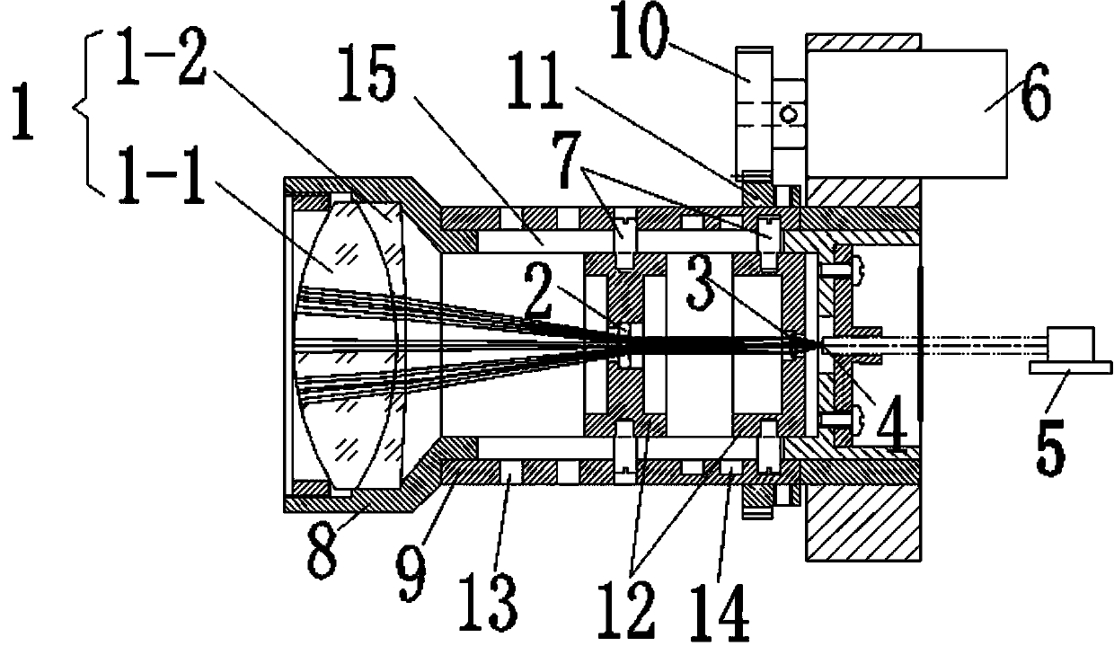
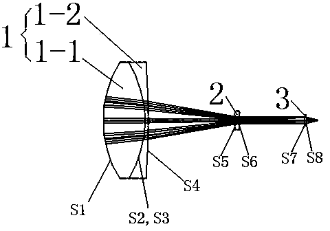
[0025] The zoom laser illuminator structure of the present invention with large zoom ratio, such as figure 1 As shown, it includes an outer lens barrel 9, an inner lens barrel 8, a fiber laser 5 and a motor 6, the fiber laser 5 passes through an optical fiber to form an optical fiber end face 4, and the inner front end of the inner lens barrel 8 is fixed with a first lens group 1, so A movable second lens 2 and a third lens 3 are sequentially arranged between the first lens group 1 and the fiber end face 4, and the second lens 2 and the third lens 3 are fixed on the lens holder 12, and the inner lens barrel 8 is located inside the outer lens barrel 9, and the lens holder 12 is in the inner lens barrel 8; the output shaft of the motor 6 is provided with a transmission gear 10, and the outer lens barrel 9 is provided with a large gear 11 meshing with the transmission gea...


PUM


Abstract

The invention discloses a large-zoom-ratio zooming laser illuminator. A first lens set is fixed. A second lens set and a third lens set can move. In the zooming process of the laser illuminator, light beams sequentially pass through the first lens set to be converged, then passes through the second lens set to be diffused and finally passes through the third lens set to be converged. The divergence angle of the light beams passing through the first lens set can be regulated by regulating the distance between the first lens set and an optical fiber end face, beam expanding can be further conducted on the divergence angle by regulating the distance between the second lens set and the first lens set, and therefore 66 or more times of focal length changes are achieved, high transmittance, high light passing quantity and easy assembly performance of the zooming laser illuminator are ensured, and the high light passing quantity of F1.8 can be achieved. The second lens set and the third lens set are quite smaller than the first lens set, and a user only needs to select a motor with small driving capacity. The first lens set which is fixed is equivalent to a device, similar to a glass window, of the zooming illuminator, and therefore the zooming illuminator can be well protected while dust is prevented from entering the large-zoom-ratio zooming laser illuminator.

Description

technical field [0001] The invention relates to a zoom laser illuminator, in particular to a zoom laser illuminator with a large zoom ratio. Background technique [0002] In the prior art, the zoom illuminator designed using the imaging principle has a clear edge of the light spot, which greatly improves the homogenization effect of the laser and the night vision illumination distance. However, the zoom laser illuminator designed using the imaging principle, such as the Chinese patent According to the document CN102252278A, the change of the spot size is realized by using the distance between the two lenses far away from the end face of the optical fiber. In this patent, the set of lenses farthest from the end face of the optical fiber is a doublet lens, and the aperture is much larger than the other two lenses. In this way, if a cemented lens with a larger diameter is driven by a motor to change the spot size, a motor with a larger driving capacity is bound to be required, ...

Claims


Application Information

Patent Timeline
Patent Type & Authority Applications(China)
IPC IPC(8): G02B7/04
Inventor 罗倩倩徐勤蒲付效奎祝传省李明陶小凯
Owner 山东神戎电子股份有限公司
Why Eureka
Try Eureka